
Fig. 22
- ID
- ZDB-FIG-190801-24
- Publication
- Nowak-Sliwinska et al., 2018 - Consensus guidelines for the use and interpretation of angiogenesis assays
- Other Figures
- All Figure Page
- Back to All Figure Page
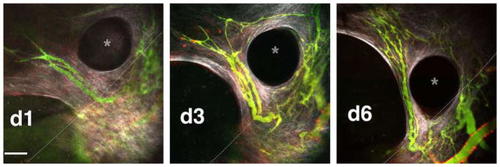
Imaging of vasculature in the cranial window preparation. Vascular sprouts entering a cranial window tissue isolation chamber. Time sequence of new vasculature (green) migrating toward the top left into a cranial window TIC, past the edge of the PDMS disk (dashed line) (imaged using MPLSM and SHG). Alignment of collagen fibers (white) is evident, and alpha-SMA+ cells can be seen on the PDMS surface (red). The vasculature (green, FITC-dextran) extends by forming perfused loops and sprouts. As the matrix remodels, the vessels also remodel as they advance. |