
- Title
-
Cytokinetic abscission is part of the midblastula transition in early zebrafish embryogenesis
- Authors
- Adar-Levor, S., Nachmias, D., Gal-Oz, S.T., Jahn, Y.M., Peyrieras, N., Zaritsky, A., Birnbaum, R.Y., Elia, N.
- Source
- Full text @ Proc. Natl. Acad. Sci. USA
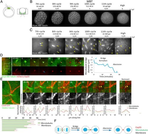
Cytokinetic abscission in zebrafish embryos at blastula stage. (A) Schematic illustration of the experimental setup used to visualize abscission in live zebrafish embryos during blastula. One-cell-stage embryos were injected with mRNA encoding for specific proteins and with HiLyte 488-Tubulin (Left), dechorionized and mounted in custom-made agar chambers (described in Methods and SI Appendix, Fig. S1B) with the animal pole facing the coverslip, and imaged using an inverted spinning disk (Right). (B, C) Whole embryos (B) and intercellular bridges (C) visualized throughout blastula stage in live embryos. Shown are selected frames from time lapse movies demonstrating mitosis at 7th to 11th cell cycle stages using tubulin labeling. Maximum intensity projection (30 Z slices at 1 µm) is shown (Movies S1 and S2). (D) Representative time frames from live imaging recordings of an embryo at the 8th to 10th cell cycles injected with HiLyte488-tubulin (green) and mRNA encoding to mCherry-cep55 (red) (Movie S3). A zoomed-out image of the two dividing cells is shown to the left. Time 0, bridge formation, was set as the first time point at which a single microtubule stalk with a packed Cep55 puncta was observed. Formation of a midbody remnant (asterisk) was defined as the completion of abscission. Plot on the right: the diameter of the microtubule stalk was measured at the rim of the midbody from bridge formation (white line, time 0) and plotted through time. Blue arrows represent bridge formation and abscission events. This analysis was repeated for each of the intercellular bridges measured in this study. (Scale bar, 10 µm.) n = 18 bridges, five embryos. (E) Representative time frames from live imaging recordings of an embryo at the 10th cell cycle injected with TAMRA-tubulin (green) and mRNA encoding CAAX-GFP (red) (Movie S4). A zoomed-out image of the two dividing cells is shown to the left. Time 0, bridge formation; asterisk, midbody remnant. Line intensities along the line drawn in the zoomed-out image are plotted for each channel at the bottom of each image. Note that the microtubule stalk (single peak, red) is surrounded by a membrane tube (two peaks, green). Midbody remnant formation (asterisk) is accompanied by decreased tubulin signal at the location of the bridge. A continuous membrane staining is observed several minutes later, representing closure of the membrane tube. (Right) An image and a line intensity plot of the midbody remnant showing that the tubulin foci is surrounded by a membrane staining. (Bottom) Measurements of intercellular bridge durations based on microtubule signal (green) and membrane signal (red) as determined for individual bridges. (Scale bar, 10 µm.) n = 8 bridges, two embryos. (F) Schematic illustration of the major steps in cytokinesis in zebrafish embryos. |
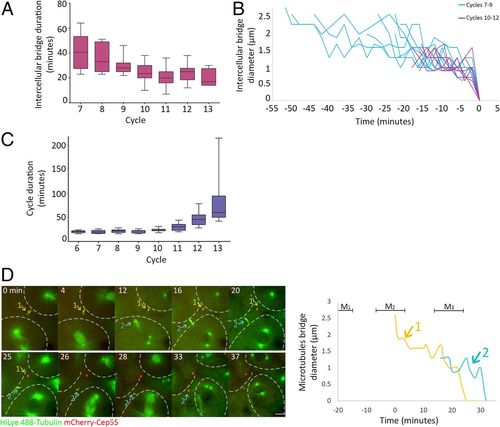
Intercellular bridges persist for longer times in early cell cycles. (A) Averaged durations of intercellular bridges (measured based on Cep55 and tubulin signal, as described in Fig. 1D) formed at different cell cycles. n = 49 bridges, five embryos. Error bars, SD. (B) Intercellular bridge diameters measured in bridges that formed before (blue) or after (purple) the 10th cell cycle. Time 0, time of abscission. (C) Averaged cell cycle durations measured in embryos at different division cycles. Values were measured for individual cells, and averaged values obtained for each embryo were plotted according to the division cycle. n = 9 embryos; error bars, SD. (D) Live imaging of dividing cells in zebrafish embryos at the 8th to 10th cell cycles. Maximum intensity projections (30 Z slices at 1 µm) taken from selected time points of a representative embryo are shown (Movie S5). Microtubules, green; Cep55, red; intercellular bridges, arrows. Cells outlines are marked with dashed lines. The durations of two intercellular bridges observed in the movie sequence are plotted to the right. Colors in plot correspond to arrows in the movie sequence. Mitosis (M); numbers refer to bridge numbers (M1, bridge 1). n = 8 cells, five embryos. (Scale bar, 10 µm.) |
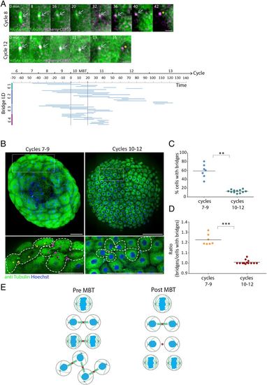
Abscission is stalled until MBT in zebrafish embryos. (A) Embryos injected with mRNA encoding to mCherry-Cep55 (magenta) and HiLyte488-tubulin (green) were imaged live, and individual intercellular bridges were tracked and measured over time (as described in Fig. 1D). (Upper) Maximum intensity projection images (10 Z slices of 0.7 µm) of representative intercellular bridges formed pre-MBT (8th cell cycle) or post-MBT (12th cell cycle), as indicated. Gray arrows, intercellular bridges; asterisks, midbody remnants. (Scale bar, 5 µm.) (Bottom) The timeline of intercellular bridges obtained from single embryos in relation to MBT. Time 0, entrance to the 10th cell cycle. Each line represents an individual intercellular bridge (from formation to abscission). (B) Tile images of whole embryos fixed pre- (7th to 9th cycles) or post-MBT (10th to 12th cycles) and stained with anti-tubulin and Hoechst. Enlarged images of the regions in dashed rectangles in upper panels are shown on the bottom. Dots, cells; arrows, intercellular bridges; dashed lines, cells outline. Clusters of connected cells are labeled with similar colors. (Scale bar, 100 µm.) (C) Percentage of cells with intercellular bridges visualized in embryos fixed at the 7th to 9th cell cycles (average = 59% ± 12.21%, n = 7 embryos) and in the 10th through 12th cell cycles (average = 12.8% ± 3.43%, n = 12 embryos). The percentage of cells in late cytokinesis in pre-MBT embryos (7th to 9th cell cycles) is significantly higher than in post-MBT embryos (10th to 12th cell cycles) according to t test (t0.05,6 = 7.921, P = 0.002). (D) The ratio of intercellular bridges per cell at late cytokinesis was measured in pre- and post-MBT embryos and plotted on the graph. Averaged ratios for pre-MBT embryos = 1.009 ± 0.019 (n = 7 embryos); post-MBT embryos = 1.22 ± 0.048 (n = 12). Ratios in pre-MBT embryos are significantly higher than in post-MBT embryos (Mann–Whitney U test, U7,9 = 0, P = 0.0002). (E) Schematic model of intercellular bridge connection in pre- and post- MBT embryos. **P = 0.001 to 0.01, ***P = 0.0001 to 0.001. |
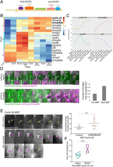
ESCRT proteins are involved in abscission during zebrafish embryogenesis. (A) Schematic representation of the canonical ESCRT cascade. Early ESCRT proteins, such as CEP55, ALIX, and TSG101, recruit late ESCRTs (CHMP1-7 and IST1) and VPS4 to the inner side of the plasma membrane where scission occurs. (B) Hierarchical clustering of the expression levels of the zygotically activated gene cyclin d1 and 17 ESCRT genes taken from RNA sequencing data from eight developmental stages [downloaded from White et al. (41)]. Rows, individual genes; columns, developmental stages. Colors in the heatmap indicate the expression levels of each gene across the samples relative to its mean expression and trimmed to range [−2, 2] (SI Appendix, Fig. S3B for raw data). Clusters 1–3, color coded to the left of the heatmap, are based on expression patterns. (C) Normalized mRNA levels obtained for Cyclin d1 and representative ESCRT genes plotted through time. x-axis, developmental stages; y-axis, normalized expression levels. (D) Embryos were injected with mRNA that encodes for Tsg101 (Upper) or Chmp4bb (Bottom), fused to mCherry (magenta) and with HiLyte 488-Tubulin (green). Shown are maximum intensity projection images of subvolumes of the cells that include the intercellular bridge (10 through 25 Z slices of 0.7 µm intervals) taken from time lapse movies of representative cells imaged in embryos at the 12th cell cycle. Both proteins localized to the intercellular bridge (gray arrow) and were detected in the midbody remnants after abscission (asterisks). Time 0, bridge formation. (Insets) Zoomed-in images of the midbody. (Scale bar, 10 µm.) (Right) A fraction of intercellular bridges exhibiting chmp4bb localization in pre- and post-MBT of embryos. Tsg101, n = 8 bridges, two embryos; chmp4bb, n = 46 bridges, three embryos. (E) Embryos were injected with morpholino oligos (control or Chmp4bb specific), and intercellular bridges were recorded through time in embryos at the 10th cell cycle. Shown are maximum intensity projection images (6 through 10 Z slices of 1 µm interval) taken from movies of representative intercellular bridges (Movie S7). Asterisks, midbody remnant. (Scale bar, 5 µm.) (Right) Intercellular bridge durations measured for individual intercellular bridges (as described in Fig. 1D) in control and knockdown (KD) embryos. Averaged bridge duration in Chmp4bb KD embryos = 40.09 ± 16.82 (n = 11 bridges, five embryos); in control embryos, averaged bridge duration = 24.11 ± 6.47 min (n = 9 bridges, three embryos). Intercellular bridge duration was significantly longer in Chmp4bb KD embryos compared to control embryos (unpaired t test with Welch's correction for unequal variances, t0.05,13 = 2.9, P = 0.012). (F) Percentage of cells with intercellular bridges in embryos at the 10th to 12th cell cycles (post-MBT). VPS4EQ-injected embryos had a significantly higher ratio than naive embryos (unpaired t test with Welch's correction for unequal variances, t0.05,14 = 2.9, 5.48, P < 0.0001). n = 22 embryos. **P = 0.001 to 0.01, ***P = 0.0001 to 0.001. |
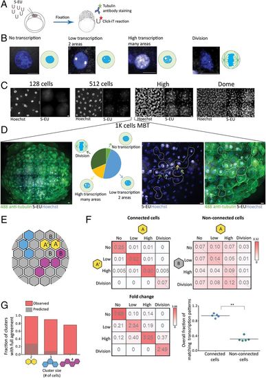
Cells connected by intercellular bridges exhibit a similar transcription pattern. (A) A schematic illustration of the experimental setup. One-cell-stage embryos were injected with 5-ethynyl uridine (5-EU) and fixed at the indicated stages. Embryos were stained with anti-tubulin (for intercellular bridge detection) and Hoechst (for nuclear detection) and click-labeled using Alexa594-azide for detection of mRNA-incorporated 5-EU. (B) Single cells labeled with 5-EU (white) and Hoechst (blue), exhibiting the 5-EU labeling patterns observed in the embryos. Transcription patterns were classified into four different stages based on 5-EU labeling: no, low, high, and dividing cells (46). (Scale bar, 10 µm.) (C) Tile images of maximum intensity projection images (15 through 30 Z slices of 1 to 1.5 µm interval) of representative regions in embryos at the indicated developmental stages. n = 4–5 embryos from each stage. (Scale bar, 10 µm.) (D) Heterogeneous transcription patterns observed in embryos at MBT. (Far Left) A tile image of a representative embryo labeled with tubulin (green), Hoechst (blue), and 5-EU (white). (Middle Left) The relative distribution of the four transcription patterns (classified in B) observed in a representative embryo (no transcription, 5%; low transcription, 48%; high transcription, 15%; and dividing cells, 32%). (Middle Right and Far Right) Enlarged images of subset regions in the embryo with high levels of cell–cell variations in transcription patterns. Different transcription patterns are marked in arrows at different colors (corresponding to arrows in the Middle Left). Clusters of interconnected cells (marked in dashed lines) were identified based on tubulin staining and were used in the analysis described in E–G. (Scale bar, 10 µm.) (E–G) Quantitative analysis of the similarity in transcription patterns observed between connected and nonconnected cells. (E) Schematic representation of an embryo at MBT. Connected cells are filled with similar colors; letters correspond to the matrixes presented in F. (F) Resemblance matrix of transcription patterns of embryos at MBT. (Top) Pairs of connected (Left) and nonconnected (Right) cells (A, A′, and A, B, respectively) were scored according to their transcription pattern, and the fraction of specific combinations of transcription patterns between cell pairs was plotted in the matrix. Color indicates probability. Data were pooled across five embryos (206 connected and 768 nonconnected cell pairs). (Bottom Left) The fold change increase in fraction of connected versus nonconnected cell pairs. (Bottom Right) The accumulated probability of agreement in transcriptional patterns in connected versus nonconnected cell pairs (values were calculated independently for each embryo, n = 5). Connected cell pairs obtained a significantly higher transcriptional agreement compared to nonconnected pairs (0.94 ± 0.05 versus 0.32 ± 0.07, respectively; Mann–Whitney U test, U5,5 = 0.8, P = 0.003). (G) Clusters of two, three, and four connected cells were scored for matched transcription patterns such that only clusters in which all cells exhibited a similar transcription pattern were considered as clusters with intracluster agreement (red bars). Values were compared to simulated data, generated as described in SI Appendix, Supplementary Methods (dashed bars). Two-cell clusters (n = 150), 98.6% versus 28%; three-cell clusters (n = 30), 90% versus 9.1%; four-cell clusters (n = 12), 76.9% versus 3.1%. **P = 0.001 to 0.01. |