
Fig. 6
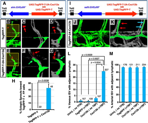
Ectopic Overexpression of Chemokine Ligands Induces Abnormal Migration of LEC (A) Diagram of constructs for spatiotemporal overexpression of either TagRFP-T + Cxcl12a (produced cotranslationally using a viral 2A peptide linker) or TagRFP-T alone (arrows indicate direction of gene expression; see Supplemental Experimental Procedures for details). (B–G) Confocal images of trunk vessels in 55 hpf Tg(fli-EGFP)y1 embryos injected with constructs as shown in (A) and treated with TBF from 30 hpf (see Supplemental Experimental Procedures). Yellow boxes in (B) and (E) indicate areas magnified in (C) and (F), respectively. Images in (D) and (G) are 3D reconstructed cross-sectional views of the same confocal data shown in (B) and (E), respectively (90° horizontal rotation). Dashed lines mark the level of the HM, where the PC normally forms. Red fluorescence (noted with red arrows) shows neural FP cells expressing TagRFP-T (B)–(D) or TagRFP-T + Cxcl12a (E)–(G). Developing lymphatics are colorized green in (C), (D), (F), and (G). Green arrows in (F) and (G) point to an ectopic lymphatic sprout extending dorsally beyond the HM toward nearby TagRFP-T + Cxcl12a-expressing FP cells. (H) Quantification of ectopic lymphatic sprout migration in segments with TagRFP-T-positive cells in embryos injected with the constructs shown in (A). Values are the mean ± SEM. The total number of secondary sprouts counted is shown above each bar. (I) Diagram of constructs for spatiotemporal overexpression of either TagRFP-T + Cxcl12b or TagRFP-T alone (arrows, direction of gene expression; see Supplemental Experimental Procedures). (J) Confocal image of ventral trunk vessels in a 5 dpf Tg(fli-EGFP)y1 embryo injected with TagRFP-T + Cxcl12b expression construct (shown in I) and treated with TBF from 55 hpf (see Supplemental Experimental Procedures). (K) Same image as in (J) with developing lymphatics colorized green (red arrows, a normal ISLVs adjacent to an aISVs; blue arrows, a mislocalized ISLVs adjacent to a vISVs). (L) Quantification of venous ISVs with an immediately adjacent ISLVs in uninjected embryos or embryos injected with constructs shown in (I) with or without TBF treatment. Values are the mean ± SEM. (M) Quantification of arterial ISVs with an immediately adjacent ISLVs in uninjected embryos or embryos injected with constructs shown in (I), with or without TBF treatment. Values are the mean ± SEM. The total number of vISVs (L) or aISVs (M) counted is shown above each bar. See also Figure S6. |
Reprinted from Developmental Cell, 22(4), Cha, Y.R., Fujita, M., Butler, M., Isogai, S., Kochhan, E., Siekmann, A.F., and Weinstein, B.M., Chemokine Signaling Directs Trunk Lymphatic Network Formation along the Preexisting Blood Vasculature, 824-836, Copyright (2012) with permission from Elsevier. Full text @ Dev. Cell