FIGURE SUMMARY
Title

Image restoration of degraded time-lapse microscopy data mediated by near-infrared imaging

Authors
Gritti, N., Power, R.M., Graves, A., Huisken, J.
Source
Full text @ Nat. Methods

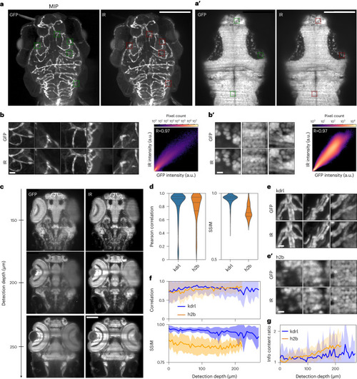
Highly selective near-infrared staining and light-sheet microscopy affords superior imaging at depth in tissue.

a, Maximum intensity projected (MIP) z stacks acquired for a fixed Tg(kdrl:GFP) (vascular marker) zebrafish larva (72 hpf) stained against GFP via conventional indirect immunostaining with AlexaFluor800 (AF800). hpf, hours post fertilization. Visible (GFP) left, NIR (AF800) right. Scale bar, 100 µm. a′, A single superficial z plane from a fixed Tg(h2b:GFP) (nuclear marker) zebrafish larva/embryo (96 hpf) stained against GFP via nanobody-conjugate CF800. Visible (GFP) left, NIR (CF800) right. Scale bar, 100 µm. b,b′, Selected superficial patches shown by the dashed boxes in a,a′, respectively (visible (GFP) top, NIR (AF800/CF800) bottom) and pixelwise correlation plots for all 125 extracted patches. Scale bar, 5 µm. a.u., arbitrary units. c, Multiple deeper z planes acquired for the same nuclear marker (h2b) zebrafish embryo/larva shown in b. Scale bar, 100 µm. d, Pearson correlation and SSIM for the full z stacks acquired for the vascular (kdrl) and nuclear (h2b) marker zebrafish from a,a′, respectively. Dashed lines represent 25/50/75th quartiles. e,e', Selected deeper patches for the vascular (kdrl) and nuclear (h2b) marker zebrafish from a,a′, respectively. Scale bar, 5 µm. f, Pearson correlation and SSIM for all patches extracted at different z planes from the full z stacks of the vascular (kdrl) and nuclear (h2b) marker zebrafish. The z depth provided is the maximum z depth into tissue for each image in the stack. The uncertainty envelope is given by the s.d. and the inner thick line represents the mean value. g, The information content gain (Methods), between the visible (GFP) and IR channels (IIR/IGFP) for all patches extracted at different z planes from the full z stacks of the vascular (kdrl) and nuclear (h2b) marker zebrafish. The uncertainty envelope is given by the s.d. and the inner thick line represents the mean value.

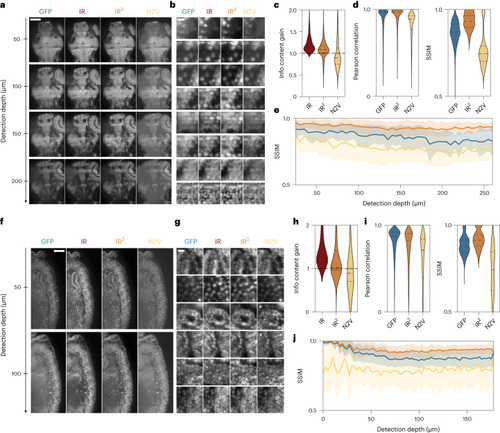
Infrared-mediated image restoration improves image quality of degraded GFP images.

a, Single GFP and IR images (left) extracted at increasing detection depth in a 96 hpf Tg(h2b:GFP) zebrafish larva restored with either IR2 or Noise2Void (N2V) (right). Scale bar, 100 µm. b, Example patches for the same zebrafish dataset shown in a arranged by increasing cell density. Scale bar, 5 µm. c, Violin plots of information content gain (relative to GFP) in patches extracted from the ground-truth (IR, dark red), IR2-reconstructed (IR2, orange) and N2V-reconstructed (N2V, yellow) images. Vertical gray lines indicate s.d. d, Pearson correlation and SSIM obtained for patches extracted in the GFP, IR2- and N2V-restored images when compared to the ground-truth image (IR). e, SSIM relative to IR image as a function of detection depth for patches extracted throughout the sample. Data are presented as mean ± s.d. f, Single z planes at increasing detection depth for a Tg(His2AV-GFP) fly larva (8 hpf) extracted from the input (GFP) and ground-truth image (IR), as well as from restored images obtained from IR2 and Noise2Void. Scale bar, 100 µm. g, Example patches for the same fly dataset shown in f. White asterisks indicate patches where artifacts were introduced or features were not reconstructed by the Noise2Void network. Scale bar, 5 µm. h, Violin plot of information content gain (relative to GFP) in patches extracted from the ground-truth (IR, dark red), IR2-reconstructed (IRIR, orange) and N2V-reconstructed (N2V, yellow) images. Vertical gray lines indicate s.d. i, Pearson correlation and SSIM relative to IR image, for GFP, infrared-mediated and Noise2Void reconstructions. j, SSIM relative to NIR images as a function of detection depth. Data are presented as mean ± s.d. In all violin plots, dashed lines represent 25/50/75th quartiles.

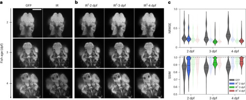
The quality of IR2 images is robust over large developmental intervals.

a, Representative GFP and IR images of a single z plane in a full 3D stack of Tg(kdrl:GFP) zebrafish larvae at 2, 3 and 4 d after fertilization. Scale bar, 100 µm. dpf, days post fertilization. b, Image reconstructions obtained from IR2 models trained with images from 2, 3 and 4 dpf zebrafish larvae. c, Quantification of image quality as measured with the NRMSE and SSIM from the GFP image as well as the images obtained after IR2 reconstruction. Values were averaged over all patches extracted from four different samples per age group. Non-transparent violin plots represent the values from the GFP images and the images reconstructed from the IR2 network matching the zebrafish age. Transparent violin plots represent reconstruction performed with networks from other developmental stages. Horizontal solid and dashed lines represent the mean and quartile values, respectively.

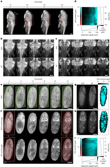
Infrared-mediated image restoration provides high-contrast deep-tissue time-lapse imaging of living biological systems.

a, 3D reconstruction of live Tg(h2b:gfp) zebrafish larva images. Orange boxes represent the regions shown in b,c. Scale bar, 100 µm. b,c, Individual z planes at detection depth of 100 µm and 250 µm, respectively for the fish larva shown in a. Endogenous GFP (top), IR2 reconstructed images (bottom). Scale bar, 100 µm. d, Kymograph representing the information content gain relative to the GFP images, for all the images in the time-lapse dataset and as a function of detection depth. Line plots to the right and the bottom represent the depth- and time-average information content gain. e, 3D reconstruction of live (Tg(His2AV-GFP)) fly larva images. Green opaque planes represent the sample sections shown in f. Scale bar, 100 µm. f, Individual z plane for the fly images shown in e. Endogenous GFP (top), IR2 reconstructed images (bottom). Red-highlighted time points are shown in g,h. Scale bar, 100 µm. g,h, Spatial mapping of the information content gain for the two individual z planes shown. Scale bar, 100 µm. i, Kymograph of the information content gain as a function of time and detection depth. Line plots represent the depth- and time-average information content gain.

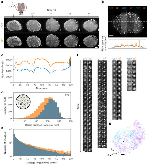
Image restoration of developing pescoid.

a, MIPs of z planes between 240 and 280 µm deep inside a pescoid (cartoon) developing over the course of approximately 10 h. Live GFP images (top) and the images reconstructed using IR2 (bottom). Scale bar, 50 µm. b, A single z plane from the volume acquired at the first time point, where GFP and IR2 images have been alternated in vertical stripes (top). The plot profile along the white dashed line in the GFP (blue) and IR2 images (orange) (bottom). Scale bar, 50 µm. c, Number of cells detected over time in the GFP (blue) and IR2 (orange) volumes. d, Number of cells detected in GFP (blue) and IR2 (orange) images at the first time point as a function of the distance from the center of mass (c.m.) (inset). e, Distribution of track lengths in GFP (blue) and IR2 (orange) time-lapse images. f, Example of images from cell tracks in GFP and IR2 time lapse. Scale bar, 5 µm. g, 3D representation of tracks longer than 50 time points, color coded for time (light blue indicates early time points and violet indicates late time points). Black lines indicate tracks represented in f. Scale bar, 50 µm.

Acknowledgments
This image is the copyrighted work of the attributed author or publisher, and ZFIN has permission only to display this image to its users. Additional permissions should be obtained from the applicable author or publisher of the image. Full text @ Nat. Methods