
- Title
-
Yolk granule fusion and microtubule aster formation regulate cortical granule translocation and exocytosis in zebrafish oocytes
- Authors
- Shamipour, S., Hofmann, L., Steccari, I., Kardos, R., Heisenberg, C.P.
- Source
- Full text @ PLoS Biol.
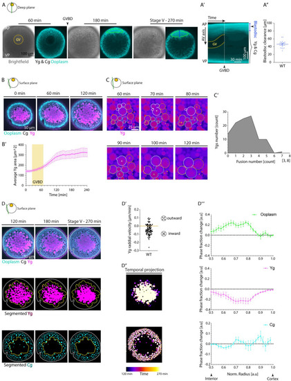
(A) Brightfield (left) and fluorescence (right) images of stage III Tg(hsp:clip170-GFP) oocytes labeling the ooplasm during oocyte maturation at 60, 180, and 270 min after maturation induction with the DHP hormone. Dashed yellow circle highlights the GV contour, and arrowhead denotes the GVBD onset. The green ROIs indicate the blastodisc region, and blue line marks the blastodisc height as measured in Fig 1A”. Ygs and Cgs are depicted by their exclusion of ooplasmic signal. ( |
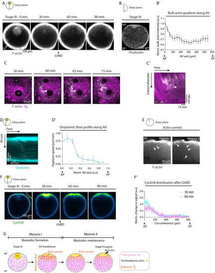
(A) Fluorescence images of stage III Tg(actb1:Utr-GFP) oocytes labeling F-actin during consecutive stages before maturation (stage III) and 30, 60, and 90 min after maturation induction with the DHP hormone. Black arrowhead denotes the GVBD onset. White arrow denotes the GCs surrounding the oocyte. The 35 μm × 35 μm white box demarcates the region for acquiring bulk actin intensity in S3B Fig. (B) Fluorescence image of a stage IV oocyte fixed, sectioned, and stained with Phalloidin to visualize and measure bulk F-actin gradient along the AV axis of the oocyte shown in (B’). (B’) Bulk actin intensity within cytoplasmic pockets normalized to its value at the AP along the AV axis, measured from fixed stage IV oocytes stained with phalloidin as in (B); (N = 3 experiments, n = 17 oocytes). See Table A in S2 Data for underlying data. (C) Fluorescence images of ooplasmic extract obtained from stage III Tg(actb1:Utr-GFP) oocytes labeling F-actin (gray) and exposed to Lysotracker to mark Ygs (magenta) during 30–75 min after maturation onset. The dashed box indicates the extract diameter used for acquiring the kymograph in (C’). The arrowheads indicate the F-actin and ooplasm enrichment. The white solid line demarcates the extract boundary. (C’) Kymograph acquired along the extract diameter in (C) as a function of time. The white dashed lines mark F-actin and ooplasmic flows, while the arrowheads indicate the F-actin and ooplasm enrichment. (D) Kymograph acquired along the AV axis of Tg(hsp:clip170-GFP) oocyte marking ooplasm as a function of time. White lines trace the flow of ooplasmic pockets over time. (D’) Ooplasmic flow profile along the AV axis, measured from the slopes of ooplasmic flow trajectories shown in (D). Normalized AV of 0 and 1 correspond to the animal and vegetal poles, respectively (N = 3, n = 17). See Table B in S2 Data for underlying data. (E) Fluorescence images of oocytes injected with 200 pg Utrophin-GFP mRNA to label F-actin during first and second meiosis corresponding to 135 and 170 min after maturation induction with the DHP hormone, respectively. White arrowheads mark actin comets forming within the blastodisc region on the surface of granules. (F) Fluorescence images of stage III oocytes injected with CyclinB-GFP mRNA before (stage III) and 30, 60, and 90 min after maturation onset. Arrowhead denotes the GVBD onset. The yellow line along the oocyte circumference (Circum) was used to acquire the intensity profiles plotted in (F’). (F’) Change in CyclinB signal normalized to its distribution at the time prior to GVBD, measured at 30 min (cyan) and 60 min (magenta) after GVBD along the oocyte circumference (the yellow line in F). Circumference of 0 and 800 μm correspond to the AP and VP, respectively (N = 2, n = 5). See Table C in S2 Data for underlying data. (G) Schematic summarizing the role of actin in ooplasmic flows and blastodisc formation. Bulk actin, initially stored within the GV, is released at the AP of the oocyte upon GVBD, thereby generating a local actin gradient. This actin gradient triggers bulk actomyosin flows towards the AP, which drags the ooplasm along, resulting in blastodisc formation. In addition, the blastodisc interface is maintained during first and second meiosis by actin comet-like structures forming on the surface of granules and—in analogy to previous observations in fertilized eggs [23]—preventing them from diffusing into the blastodisc region. Schematics in each panel demarcate the imaging plane used for obtaining the images in that panel. Error bars, SEM. AP, animal pole; AV, animal-vegetal; GC, granulosa cell; GV, germinal vesicle; GVBD, germinal vesicle breakdown; VP, vegetal pole; Ygs, yolk granules. |
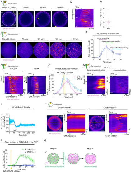
(A) Fluorescence images of stage III Tg(Xla.Eef1a1:dclk2a-GFP) oocytes labeling microtubules before (stage III) and 70, 85, and 100 min after maturation onset. Arrowheads mark the propagating front of the microtubule aster formation wave. The circumferential (Circum) line in the first panel indicates the region used for acquiring the kymograph in (A’). (A’) Kymograph acquired along the circumference of the oocyte shown in (A) as a function of time. Dashed lines mark the leading and trailing edges of the microtubule aster formation wave. (A”) Speed of microtubule aster formation wave along the oocyte circumference, measured from kymographs as shown in (A’); N = 9 experiments, n = 16 oocytes. See Table A in S3 Data for underlying data. (B) Maximum fluorescence intensity projection of high-resolution images of stage III Tg(Xla.Eef1a1:dclk2a-GFP) oocytes labeling microtubules during consecutive stages before (stage III) and 70, 85, 100, and 140 min after maturation onset. (B’) Microtubule aster number as a function of time. Aster assembly during the second hour after maturation onset is followed by initially rapid and then slower disassembly phases (N = 2, n = 8). See Table B in S3 Data for underlying data. (C) Kymographs acquired along the AV axis of Tg(Xla.Eef1a1:dclk2a-GFP) oocytes exposed to DMSO (control, left) or 700 μM CHX (right) as a function of time. Arrowheads mark the time point of oocyte exposure to DMSO/CHX. Dashed lines mark the leading and trailing edges of the microtubule aster formation wave. (C’) Microtubule aster number as a function of time for Tg(Xla.Eef1a1:dclk2a-GFP) oocytes exposed to DMSO (cyan, N = 2, n = 8) or CHX (magenta, N = 2, n = 9). The yellow box indicates the time window of oocyte exposure to DMSO or CHX in the respective experiments. See Table C in S3 Data for underlying data. (D) Kymographs acquired along the lateral (left) and AV (right) axis of exemplary Tg(Xla.Eef1a1:dclk2a-GFP) oocytes exposed to Cili D as a function of time demonstrating large-scale contractions and abnormal aster formation, respectively. (E) Microtubule intensity measured in a 50 pix-wide region at the blastodisc in the vicinity of the GV over time normalized to intensity values at GVBD onset (N = 2, n = 9). See Table D in S3 Data for underlying data. (F) Fluorescent images of stage III Tg(Xla.Eef1a1:dclk2a-GFP) oocytes exposed to DMSO (control, left) or Colchi (right) for 240 min in the absence of DHP (immature oocyte). The orange dashed boxes denote the lateral regions used for obtaining the kymographs shown on the right. The panels on the right indicate the kymographs of microtubule intensity along the lateral axis of the oocytes shown on the left as a function of time. The green arrowheads denote the time point of oocyte exposure to DMSO or Colchi. (F’) Microtubule aster number as a function of time for oocytes exposed to DMSO (blue, N = 3, n = 14) or Colchi (green, N = 3, n = 13) without DHP (immature oocytes). The arrowhead denotes the time point of oocyte exposure to DMSO or Colchi. See Table E in S3 Data for underlying data. (G) Schematic summarizing the microtubule network transformation taking place during oocyte maturation. A uniform microtubule network encompassing the ooplasm of the immature oocytes reorganizes into numerous microtubule asters in a wave-like fashion from the AP to the VP of the oocyte. This network transformation relies on the partial depolymerization of the microtubule network initiated by GVBD at the AP of the oocyte. Schematics in each panel demarcate the imaging plane used for obtaining the images in that panel. Error bars, SEM. AP, animal pole; AV, animal-vegetal; CHX, Cycloheximide; Cili D, Ciliobrevin D; Colchi, Colchicine; GV, germinal vesicle; GVBD, germinal vesicle breakdown; VP, vegetal pole; WT, wild-type; Ygs, yolk granules. |
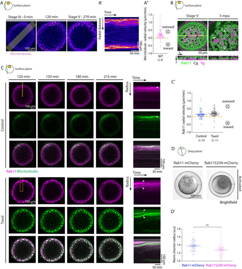
(A) Left: Fluorescence images of stage III Tg(Xla.Eef1a1:dclk2a-GFP) oocytes labeling microtubules before (stage III) and 120 and 270 min after maturation onset. The lateral line indicates the region used for acquiring the kymograph in (A’). (A’) Kymograph of microtubule intensity along the lateral axis of the oocyte shown in (A) as a function of time. (A”) Microtubule aster radial velocity during maturation onset (N = 2 experiments, n = 8 oocytes). See Table A in S4 Data for underlying data. (B) Fluorescence images of Tg(actb2:Rab11a-NeonGreen) oocytes marking Rab11-positive vesicles (green) and exposed to Lysotracker to label Ygs (magenta) at stage V (mature oocyte/egg, left) and 5 min after activation (mpa) with E3 medium (right). Cgs (black) are identified by their exclusion of Lysotracker and the ooplasmic signal. The yellow line indicates the region used for displaying the orthogonal view (bottom images). Asterisks mark exemplary Cg undergoing exocytosis, and arrowheads denote the localization of Rab11 on Cg prior to/during their exocytosis. (C) Left: Fluorescence images of stage III Tg(actb2:Rab11a-NeonGreen) oocytes marking Rab11-positive vesicles (magenta, top rows) and injected with 400 pg of DCLK-mKO2 mRNA to label microtubules (green, middle rows) 120, 150, 180, and 215 min after maturation onset in control oocytes (WT, top panels) or oocytes exposed to 50 μM Taxol (bottom panels). Overlaid images are shown in the bottom rows. Dashed lines indicate the regions used for acquiring kymographs on the right. Right: Kymographs acquired along the marked area of the oocytes shown on the left as a function of time. Arrowheads point at exemplary Rab11-positive vesicles or microtubule asters moving towards the cortex. (C’) Rab11 radial velocity during maturation onset for control oocytes (left, N = 2, n = 10) and oocytes exposed to 50 μM Taxol (right, N = 3, n = 11). See Table B in S4 Data for underlying data. (D) Brightfield images of oocytes injected with 350 pg of Rab11-mcherry (left) or Rab11S25N-mCherry (right; DN) mRNA, induced to undergo oocyte maturation for 270 min and activated consequently by exposure to E3 medium for 30 min. Black lines demarcate the distance between the egg and its overlaying chorion. (D’) Chorion elevation, measured as chorion diameter normalized to the oocyte diameter, of oocytes injected with 350 pg of Rab11-mcherry (blue, control, N = 3, n = 42) or Rab11S25N-mCherry (magenta, N = 3, n = 46) mRNA. See Table C in S4 Data for underlying data. Schematics in each panel demarcate the imaging plane used for obtaining the images in that panel. Error bars, SEM. Mann–Whitney test, **p = 0.001. Cgs, cortical granules; DN, dominant negative; WT, wild-type; Ygs, yolk granules. |
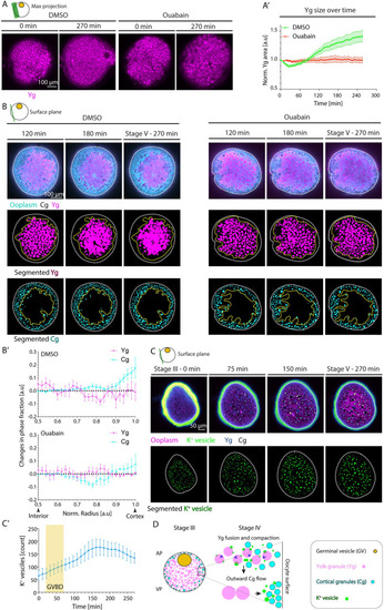
(A) Maximum fluorescence intensity projection of oocytes exposed to DMSO (left) or Ouabain (right) and Lysotracker for labeling Ygs before (stage III) and 270 min after maturation onset. (A’) Average Yg cross-sectional area normalized to its value at stage III as a function of time during oocyte maturation for oocytes exposed to DMSO (green, N = 3 experiments, n = 15 oocytes) or Ouabain (red, N = 3, n = 14). See Table A in S5 Data for underlying data. (B) Fluorescence images of DMSO-treated (left panels) and Ouabain-treated (right panels) stage III Tg(hsp:clip170-GFP) oocytes labeling ooplasm (cyan) and exposed to Lysotracker to mark Yg (magenta) and Cgs (black, identified by their exclusion of both Clip-170-GFP and Lysotracker) at 120, 180, and 270 min after maturation onset (top rows). Images in the middle and bottom rows show segmented Yg and Cg, respectively, obtained from the images in the first rows. White dashed lines mark the oocyte outline. Yellow dashed lines denote the initial distribution of Yg in the middle rows and the final distribution of Cg in the bottom rows. (B’) Changes in phase fractions of Yg (magenta) and Cg (cyan) for oocytes exposed to DMSO (top, N = 3, n = 9) or Ouabain (bottom, N = 2, n = 8) between 120 and 270 min after maturation onset. Normalized (norm) radii of 0.5 and 1 correspond to the oocyte interior and cortex, respectively. See Table B in S5 Data for underlying data. (C) Top row: Fluorescence images of stage III oocytes injected with K+ indicator (K+-Green, green) and Dextran Alexa Fluor 647 to mark ooplasm (magenta) before (stage III) and 75, 150, and 270 min after maturation onset. Cgs (black) are identified by their exclusion of both Dextran and K+-Green. The vesicles enriched with K+ fused with each other and with Yg, thereby increasing their internal K+ concentration and hence becoming dark blue (in Green-Fire-Blue Lookup Table). Bottom row: Segmented K+ vesicles identified from the images in the top row. White dashed lines mark the oocyte outline. (C’) Number of K+ vesicles in superficial stacks of the oocyte as in (C) as a function of time (N = 2, n = 8). Yellow box indicates the period during which GVBD takes place. See Table C in S5 Data for underlying data. (D) Schematic summarizing the role of Yg fusion in ooplasmic reorganizations during zebrafish oocyte maturation. GVBD leads to Yg fusion and compaction by triggering a Na+/K+ ATPase-dependent increase in the concentration of K+ within Yg. The fusion and compaction of Yg to the oocyte center, in turn, leads to ooplasm flows directed towards the oocyte surface. These ooplasmic flows, in turn, carry along Cg, thereby moving them closer to the cortex. Schematics in each panel demarcate the imaging plane used for obtaining the images in that panel. Error bars, SEM. Cg, cortical granule; GVBD, germinal vesicle breakdown; Yg, yolk granule. |