FIGURE SUMMARY
Title

µSPIM toolset: A software platform for selective plane illumination microscopy

Authors
Saska, D., Pichler, P., Qian, C., Buckley, C.L., Lagnado, L.
Source
Full text @ J. Neurosci. Methods

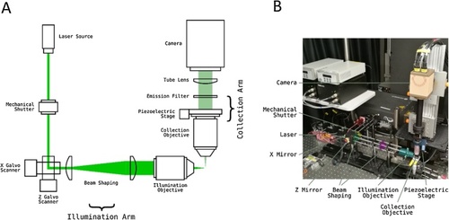
Light-Sheet Microscope Implementation.

(A) Diagram outlining light-sheet microscope with two mirror galvanometers and a stationary sample. The light sheet is created from a laser beam by the’ X Galvo mirror’. The’ Z Galvo mirror’ then moves the sheet through the sample to create volumetric excitation. This is synchronized with a Piezoelectric stage that moves the imaging objective so that the excitation plane always coincides with the imaging plane. (B) A photo of an example light-sheet microscope setup with one light-sheet path. The main components are colour coded.

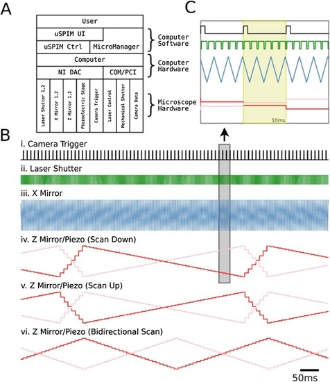
Light-Sheet Microscope Hardware Control: (A) Interaction of different components of the μSPIM Toolset-based setup in a typical acquisition setup. μSPIM Toolset provides control and synchronization of hardware through NI DAC with MicroManager controlling the camera and mechanical shutters through PCI and COM ports. (B) Traces of the command signals for a volume acquisition with 43 planes showing camera trigger (i.), laser shutter (ii.), X mirror signal (iii.), Z mirror (red) and Piezo (pink) signals for Scan Down (iv.), Scan Up (v.) and Bidirectional (vi.) acquisition modes generate by the μSPIM control software. (C) Magnification of boxed region in B with yellow region showing a single plane signal. Laser shutter signal is a result of a recording with Edge Masks enabled.

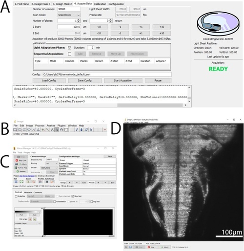
μSPIM Toolset User Interface. Following a common MicroManager design, the control interface is separated into several components: μSPIM Toolset-provided plugin window with control over the light-sheet generation including calibration and acquisition routines shown in A, basic ImageJ tools shown in B and MicroManager interface providing control over the acquisition hardware shown in C and live view of the camera shown in D. The shown user interface has been captured during the acquisition from a 7 dpf larval zebrafish from the Tg(elavl3:H2B-GCaMP6f) transgenic line.

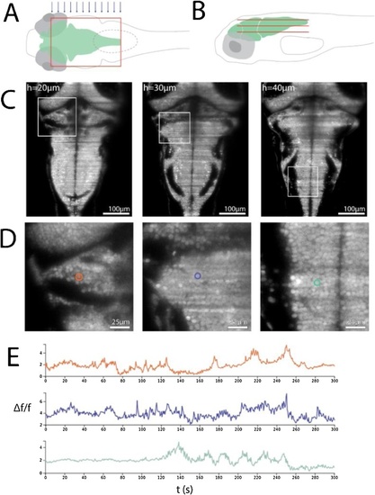
Imaging larval zebrafish: (A and B). Schematic of a single light sheet covering the hindbrain of a larval zebrafish from above (A) as well as a number of light sheets (constituting a volume) from the side (B, sheet size and spacing are not to scale). (C) Transgenic zebrafish expressing the calcium reporter GCaMP6f in the cell nuclei of all neurons (Tg(elavl3:H2B-GCaMP6f)) were embedded in agarose and positioned so that the laser entered the brain from the side (blue arrows in A). Representative sections of the volume taken at 20, 30 and 40 μm depths at a frequency of 1.6 volumes/sec and an integration time of 10.2 ms per section. The step size was 2 μm, hence representative sections are 5 sections apart. The laser was set to 1.8 mW. (D) magnified view of boxed areas in C. Single cell nuclei are clearly visible and three examples are highlighted. (E) Activity of single cells highlighted in D.

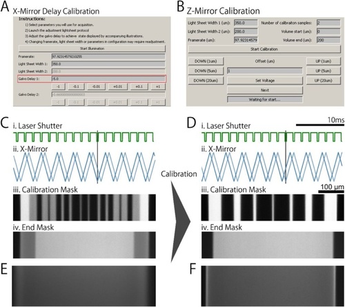
μSPIM Toolset Calibration μSPIM Toolset provides the user with calibration tools which can be used to assess and correct the performance of the individual microscope elements. (A) and (B) show the calibration interface for X mirror with respect to the laser shutter when using masks and for Z mirror, respectively. (C) The movement of the X mirror galvanometer lags behind the supplied signal, resulting in artefacts when using laser masks. (i.) shows the laser shutter signal (green) and (ii.) shows the X mirror signal (blue) and actual mirror movement (light blue). Black bar highlights the misalignment between the shutter signal and mirror movement when the X mirror signal is not calibrated and no delay is introduced. (iii.) shows a mask used for calibration, emphasizing the difference between uncalibrated and calibrated system. (iv.) shows the corresponding light sheet produced with poor calibration for the mask signal in (i.). (D) is analogous to (C), showing a well calibrated system where the laser shutter (i.) is synchronized X mirror movement (ii.), producing overlapping masks shown in (iii.) and (iv). (E) Uncalibrated Z-Mirror results in loss of focus through the volume. (F) After calibration, the light sheet is always in focus throughout the volume scan. All figures illustrating the light sheet in both uncalibrated and calibrated scenarios were acquired by scanning the laser through a fluoroscein solution.

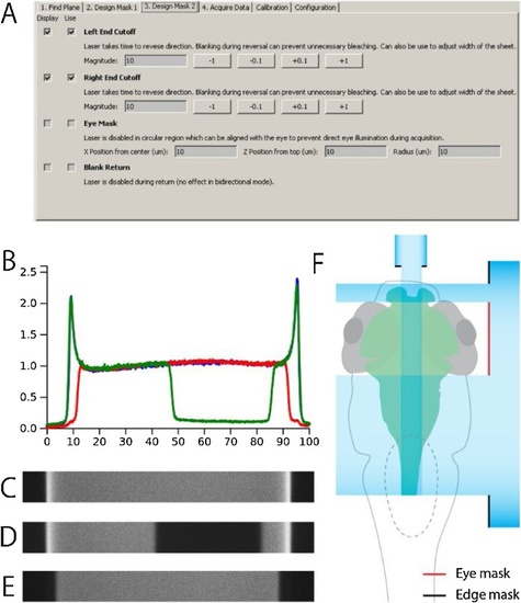
Light-Sheet Laser Masks. A. User Interface used to define laser masks allowing the user to display and use a number of masks for recordings: Edge masks help eliminate excess light during laser return as visible in D (with Edge masks enabled) compared to C (without any masks), Eye Mask allowing to turn the laser off in a specific region (such as eye of larval zebrafish) and Blank Return which turns the laser off during return (flyback), avoiding unnecessary photobleaching of the sample. B The median-normalized luminance intensity profiles of a light sheet in Fluorescein with no mask applied (blue, shown in C), edge masks (red, shown in D) and eye mask (green, shown in E). F. An illustration of how the ‘edge’ and ‘eye’ masks could be used in the context of imaging the brain of a larval zebrafish while minimizing illumination of the retina.

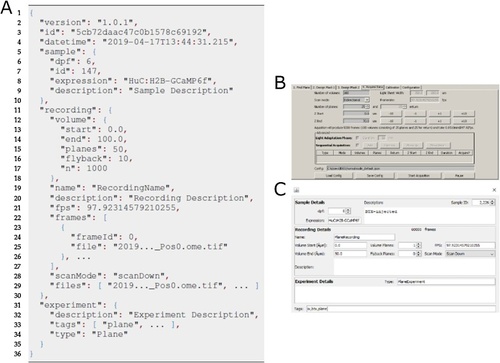
Acquisition using μSPIM Toolset & Output Data Format. μSPIM Toolset generates a separate metadata file (shown in A), supplementing metadata supplied by the MicroManager platform. The generated data contains information detailing the settings of the acquisition (such as the height of the recorded plane or number of planes in the recorded volume) based on the parameters set by the user in B. This information can be supplemented by the user to contain information about the sample imaged, comments about the experiment protocol as well as the recording itself to aid cataloguing of the data.

Acknowledgments
This image is the copyrighted work of the attributed author or publisher, and ZFIN has permission only to display this image to its users. Additional permissions should be obtained from the applicable author or publisher of the image. Full text @ J. Neurosci. Methods