
Fig. 2
- ID
- ZDB-FIG-240223-79
- Publication
- Burton et al., 2023 - Full-field exposure of larval zebrafish to narrow waveband LED light sources at defined power and energy for optogenetic applications
- Other Figures
- All Figure Page
- Back to All Figure Page
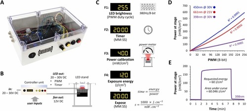
Control of irradiance, time, and radiant exposure. A: Photograph of the controller unit. B: Diagram showing the external connections of the controller unit. C: The four functions provided by the controller: F1, adjustment of LED PWM to control mean irradiance (power) at the sample plane; F2, timed exposure; F3, input irradiance calibration in mW/cm2 from external power meter; F4, automatic delivery of specified radiant exposure (energy) in J/cm2 based on calibration input in F3. D: Relationship between pulse width modulation duty cycle (x-axis; adjusted using function F1) and power at stage (y-axis) for three different LED arrays, 398 nm (purple), 450 nm (blue), 661 nm (red). Correlation coefficients are shown for each LED. E: Example automated energy exposure using a 398 nm UVA LED array. The power of 180 mW/cm2 was measured at the stage using a power meter, entered into the controller unit using function F3, then an exposure of 60 J/cm2 was requested using function F4. The graph shows the output from the power meter over time; the exposure was started 2 min into the recording. The area under the curve was calculated to compare the requested and actual light exposure. |