FIGURE

Fig. 4

ID
ZDB-FIG-221031-16
Publication
Durrer et al., 2022 - A robot-assisted acoustofluidic end effector
Other Figures
All Figure Page
Back to All Figure Page
Fig. 4

Arbitrary controlled motion of the mobile microvortex generator and design of the liquid pump.

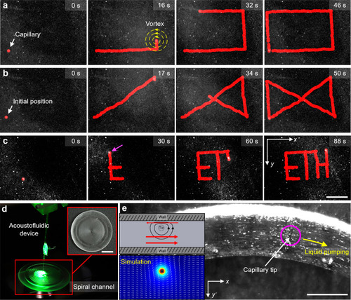
Image sequences depicting the robot-assisted acoustofluidic device executing automated patterns (here the red marking represents the path of the capillary tip and yellow concentric circles represents the vortex generated) (see Supplementary Movie 6): a a rectangle, b an hourglass, and c letters creating the acronym “ETH.” d Photograph showing the RAEE-based microfluidic liquid pump, comprised of an acoustofluidic device and a 3D-printed PDMS-based fluidic channel (see Supplementary Movie 10). d Transformation of the mobile microvortex into a LOC micropump upon immersion of the acoustofluidic device into a 3D-printed spiral fluidic channel. e The vortices produced at an excitation frequency of 134 kHz and amplitude of 10 VPP generated liquid pumping in the left-to-right direction (the magenta circle represents the capillary tip position and yellow arrow represents the liquid pumping direction) (see Supplementary Movie 10). The top inset demonstrates the pumping mechanism (here the red arrow represents the direction of particle motion in that region). The bottom inset illustrates the COMSOL simulation of fluid pumping when the capillary tip was introduced adjacent to the wall. Scale bar ac: 400 µm, scale bar d: 10 mm, scale bar e: 200 µm.

Expression Data

Expression Detail
Antibody Labeling
Phenotype Data

Phenotype Detail
Acknowledgments
This image is the copyrighted work of the attributed author or publisher, and ZFIN has permission only to display this image to its users. Additional permissions should be obtained from the applicable author or publisher of the image. Full text @ Nat. Commun.