
Fig. 1
- ID
- ZDB-FIG-210713-1
- Publication
- Qin et al., 2021 - In-vivo 3D imaging of Zebrafish's intersegmental vessel development by a bi-directional light-sheet illumination microscope
- Other Figures
- All Figure Page
- Back to All Figure Page
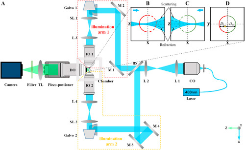
Schematic diagram of bi-directional light-sheet illumination microscope. (A) L1-L4, lens. M1-M4: Mirrors; CO: collimation objective; BS: beam split; SL1-SL2: scanning lens; Gavlo1-Gavol2: Gavlo mirror pairs; IO1-IO2: illumination objectives; DO: detection objective; TL: tube-lens. (B)–(C) The spreading of the light sheet caused by sample scattering. The blue arrows indicate the illuminating direction. (D) The weighted fusion of the two images from left- and right-illuminated light sheets. For the image generated by illuminating from the left side, only the left half of the outline (red solid line) remains, and the other half is replaced by the right-side outline (green solid line) generated by right illumination. (For interpretation of the references to colour in this figure legend, the reader is referred to the Web version of this article.) |