
- Title
-
From inflation to flotation: contribution of the swimbladder to whole-body density and swimming depth during development of the zebrafish (Danio rerio)
- Authors
- Lindsey, B.W., Smith, F.M., and Croll, R.P.
- Source
- Full text @ Zebrafish
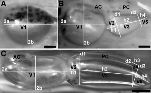
Photomicrographs of lateral views of representative swimbladders (anterior is left, dorsal is up) illustrating the overlay and linear dimensions of geometric shapes used to estimate swimbladder volume as explained in Table 1. (A) Single-chambered swimbladder approximated by a rotary prolate ellipsoid (V1). (B) LDC and (C) adult swimbladders showing the anterior (AC) chamber approximated by VI and the posterior chamber (PC) approximated by the sum of the combination of volumes V2–V5. For an explanation of equations see Table 1. Scale bars: (A, B) 0.2 mm; (C) 0.5 mm. |
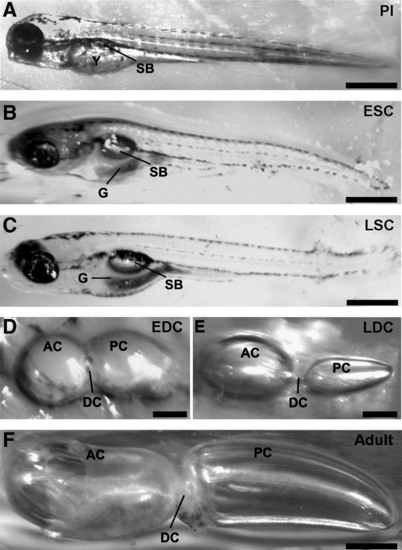
Photomicrographs of the stages of swimbladder development as viewed through the transparent body wall of larvae (A–C) or following excision from the coelomic cavity (D–F). All images show left lateral view. (A) Preinflation (PI) stage larva showing the location of the uninflated swimbladder (SB) in relation to the yolk sac (Y). (B) Early single-chamber (ESC) stage larva showing the inflated swimbladder adjacent to the developing gut (G). (C) Late single-chamber (LSC) stage larva showing the ovoid shape of the swimbladder in the coelomic cavity. (D) Early double-chamber (EDC) stage swimbladder displaying the anterior (AC) and posterior (PC) chambers connected by a wide ductus communicans (DC). (E) Late double-chamber (LDC) stage swimbladder showing the enlarged anterior chamber and constriction of the ductus communicans. (F) Adult swimbladder showing the ellipsoid-shaped anterior chamber and elongated posterior chamber. Scale bars: (A–C, F) 0.5 mm; (D, E) 0.2 mm. |
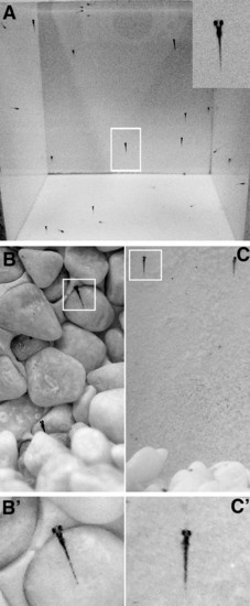
Images of larval zebrafish during swim-up behavior (A) and substrate adhesion (B, C). (A) Front view of a 9-cm-deep tank showing the vertical orientation of larvae along control tank walls during swim-up. Inset shows a typical larva with head oriented upward. (B, C) Zebrafish larvae attached to vertical rock (B, inset B′, n = 7) and sand (C, inset C′, n = 6) substrates at the PI stage. On both experimental substrates, larvae adhered in the same manner as in the control tank (A), with their heads oriented upward. Regions enclosed in boxes in B and C depict the location of insets in B′ and C′. |