IMAGE

Fig. 3

ID
ZDB-IMAGE-230817-3
Source
Figures for Ye et al., 2023
Image
Figure Caption

Fig. 3

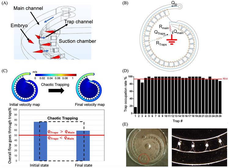
The zebrafish embryo trapping principles and validations. A The schematic showing the torpedo-shaped embryos are dragged into the traps due to the hydrodynamic suction force. B The simplified circular analogy for the multi-depth spiral device showing the parallel trapping and source and sink configurations for the design. C The CFD simulations for initial and final fluidic conditions for the trapping process. The possibility for the embryo trapping retains during the trapping process as the overall flowrate goes through the traps is always higher than the flowrate passes through the main channel. Inlet flowrate is set to be 10 ml/min. D The trap occupation rate for each individual traps (N= 24, n=624). The red line indicates the overall average trap occupation rate. 36 hpf UV treated embryo with body length around 2 mm are used in the trapping validation experiments. E Microscopy images showing the zebrafish embryos are encapsulated by the PBST droplets inside the traps due to the presence of the Laplace pressure

Acknowledgments
This image is the copyrighted work of the attributed author or publisher, and ZFIN has permission only to display this image to its users. Additional permissions should be obtained from the applicable author or publisher of the image. Full text @ Biomed. Microdevices.