
Fig. 2
- ID
- ZDB-IMAGE-200601-17
- Publication
- Taylor et al., 2019 - Adaptive prospective optical gating enables day-long 3D time-lapse imaging of the beating embryonic zebrafish heart
- All Figures
- Figures for Taylor et al., 2019
|
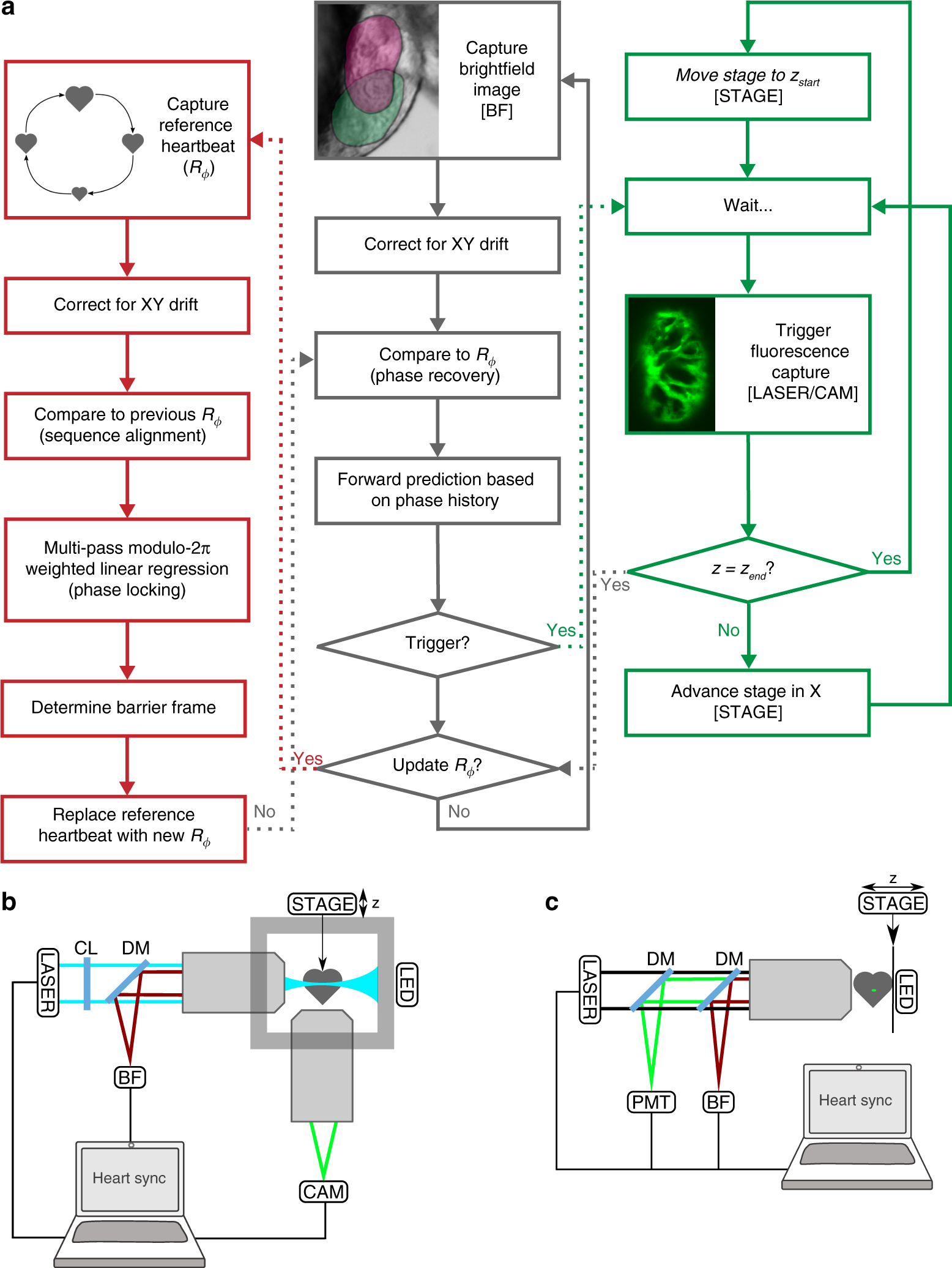
Fig. 2 Adaptive prospective optical gating permits day-long, phase-locked cardiac imaging. a Summary flow chart for adaptive prospective optical gating. Each column represents a separate thread running concurrently on the computer. The core prospective optical gating algorithm (centre, grey) identifies the current cardiac phase using the brightfield channel, and computes the correct future trigger time. The day-long phase locking algorithm (left, red) enables the system to cope with developmental-scale changes in cardiac morphology and size. The optical gating algorithms are integrated with fluorescence 𝑧-stack acquisition and stage movement (right, green). Square brackets refer to hardware components in the schematic diagrams below. b, c Simplified schematics of the custom light sheet microscope (b) and commercial two-photon microscope (c) used in this paper, highlighting the key components for adaptive prospective optical gating. Fluorescence (excited by LASER) is imaged onto a triggerable scientific camera (CAM) or photomultiplier (PMT). An infrared light source (LED) provides illumination for a brightfield camera (BF); in b this receives light collected through the laser launch objective, for reasons explained in the main text. A full optical diagram for b can be found in Supplementary Fig. 1. Other components: STAGE motorised z-stage; CL cylindrical lens; DM dichroic mirror to separate different light wavelengths