
- Title
-
In vivo quantification of mechanical properties of caudal fins in adult zebrafish.
- Authors
- Puri, S., Aegerter-Wilmsen, T., Jaźwińska, A., Aegerter, C.M.
- Source
- Full text @ J. Exp. Biol.
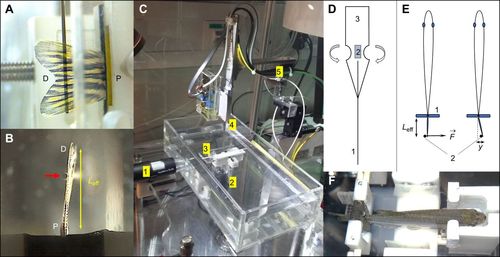
Overview of the setup showing the basic principle of measurement. (A) Side view of a lined force attack from the deflection pin onto the fin surface (D, distal end of the fin; P, proximal end of the fin). (B) Bottom view showing the pin (red arrow) at a certain effective beam length from the fixation (black foam pads). (C) Overall view of the measurement setup showing the water basin, two camera positions (1 and 2) as in A and B, respectively, a fish-holding device (3), as also shown in F, and the sensor construct (4) mounted onto piezo-based positioners (5). (D) Design of the sensor construct with strain gauges (2) mounted onto a spring sheet (3), with the deflection pin (1) that leads to the base of the strain gauges to increase the effective bending moment together with the specialized geometry of the spring sheet (3). (E) Measurement principle illustrating the deflection pin (2) applying a force ( |

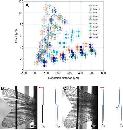
Elasticity measurements for the interray tissues. (A) Force–deflection curves for five fish. Open symbols indicate measurements performed on intact tissues (B), whereas filled symbols show the results for surgically disrupted tissues (C). Error bars for deflection distance correspond to standard deviations (±20 µm), equally for force (±5 µN). Measurements were performed at the same positions in each fin, once between the 4th and 5th ray (B,C) and once between the 6th and 7th ray (not shown). The illustrations B1, B2, C1 and C2 represent front views. B1 and C1 represent the starting position, before a deflection to the left (indicated by a red arrow) stretches the interray tissue (B2), resulting in the configurations B2 and C2, respectively. |
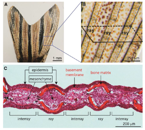
The structural and histological organization of a caudal fin in adult zebrafish. (A-B) Live-imaging of the caudal fin. (A) The adult fin has a bi-lobed morphology, supported by an array of bones, which occasionally bifurcate. (B) Higher magnification of the framed area in (A) displays segmented bone-containing rays, called lepidotrichia, which are spanned by soft interray tissue. The schematic parallelogram depicts a transversal sectioning plane for histological analysis. (C) Transversal section of a fixed fin stained with Haematoxylin (nuclei, violet) and Eosin (cytoplasm, pink/magenta; extracellular matrix, red/orange). Rays are supported by a pair of concave bones underneath the epidermis. The interray tissue is devoid of skeletal elements and the epidermis is supported by the thickened basement membrane. The mesenchymal tissue fills the inner part of the fin, and it contains fibroblasts, extracellular matrix, nerves and blood vessels. |

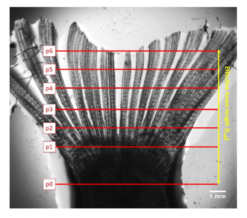
Proximal-distal deflection positions in normal fins. The red lines (positions p1-p6) indicate the 6 deflection positions along the fin. A plane of ray bifurcations can be seen at about 3mm (p2-p3) from the fixation point (p0). The effective beam length (Leff) is used in Eq.1. |
Proximal-distal deflection positions in surgically disrupted fins. Shape of a zebrafish fin where the interray tissue has been surgically removed. The bending stiffness of such a fin is only determined by the stiffness of the rays. |