
Figure 1.
- ID
- ZDB-IMAGE-231024-2
- Publication
- Zhu et al., 2023 - SAMPL is a high-throughput solution to study unconstrained vertical behavior in small animals
- All Figures
- Figures for Zhu et al., 2023
|
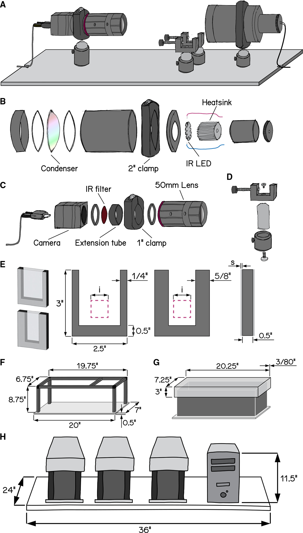
Figure 1. Schematic illustrations of SAMPL hardware design
(A) Overview of the apparatus without aluminum rails, side panels, and the top panel. Equipment modules mounted on the breadboard are, from left to right, IR camera and lens, chamber holders, and IR illumination module.
(B) Exploded-view drawing of the IR illumination module.
(C) Exploded-view drawing of the camera and lens module.
(D) Exploded-view drawing of a chamber holder.
(E) Design of fish chambers. From left to right: 3D illustration of a standard chamber (top) and a narrow chamber (bottom), front view of the U-shaped acrylic middle piece for the chambers, and side view of the chamber. Pink squares illustrate the recording field of view. i = 20 mm; s = 1.5 mm.
(F) Dimensions of the apparatus frame and breadboard.
(G) Design and dimensions of the apparatus lid.
(H) Schematic illustration of a set of three SAMPL apparatus and a small-form-factor computer case on a 24″ × 36″ shelf.
See also