IMAGE

Figure 10

ID
ZDB-IMAGE-200716-63
Source
Figures for Keller et al., 2020
Image
Figure Caption

Figure 10

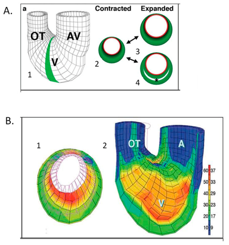
Computational modeling of embryonic heart wall strains. (A) Model and problem orientation. 1. Three-dimensional mesh diagram of tubular chick heart exterior with atrioventricular (AV) canal, ventricular (V) loop and outflow tract (OT) with the shaded 2D cross-sectional plane selected for further analysis; 2. diagramed in the contracted state with a subendocardial layer (red) and muscle cross-sectional area (green). Two plausible expanded states are shown for a solid wall (3) or a wall with trabecular spaces (4). (B) Finite element modeling of stage 21 chick heart with a four-layer mesh shows greater strain (red) along inner layers at maximal expansion. 1. (A) Two-dimensional section across the ventricular loop; 2. (A) Three-dimensional global mesh oriented as in A1 with the anterior half removed to show interior surfaces. The scale shows the percentage elongation of initially unloaded elements along the left, with corresponding fractional shortening (%) shown to the right. This was adapted with permission [136].

Acknowledgments
This image is the copyrighted work of the attributed author or publisher, and ZFIN has permission only to display this image to its users. Additional permissions should be obtained from the applicable author or publisher of the image. Full text @ J Cardiovasc Dev Dis