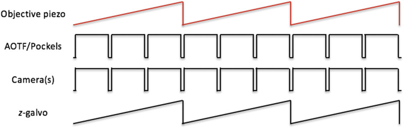
IMAGE

FIG. 6.

ID
ZDB-IMAGE-200606-6
Source
Figures for Keomanee-Dizon et al., 2020
Image
Figure Caption

FIG. 6.

Schematic of control signal sequences for objective-scanning mode. The analog signal representing the position of the objective piezo collar is used as the master timing signal to generate control signals for the imaging cameras (both the fluorescence camera and behavior camera). The timing output of the fluorescence camera controls the AOTF/Pockels. The number of pulses driving the cameras, shown as 3 in the schematic here, determines the number of individual z-plane images to be recorded during a single z-scan cycle over the sample. The position signal of the objective piezo collar, appropriately scaled by a scaling amplifier, is also used to drive the z-galvo.

Acknowledgments
This image is the copyrighted work of the attributed author or publisher, and ZFIN has permission only to display this image to its users. Additional permissions should be obtained from the applicable author or publisher of the image. Full text @ Rev. Sci. Instrum.