
|
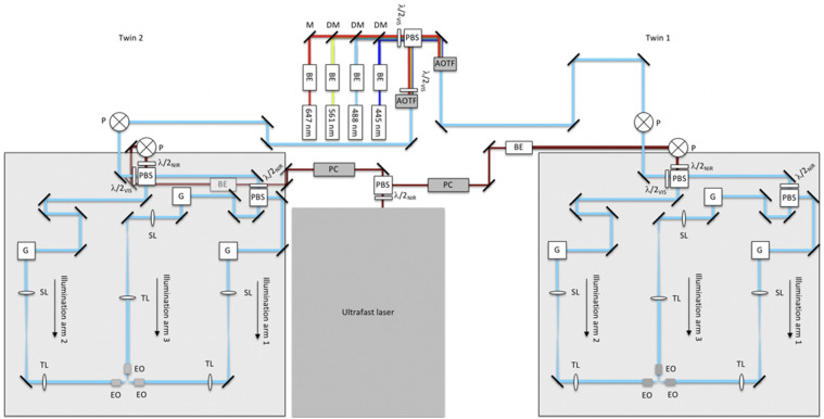
FIG. 3.
Schematic diagram of multi-laser and illumination-scanning optics subsystems of the instrument. Visible light from the continuous-wave laser bank is fed into microscope-twin 1 (right) and microscope-twin 2 (left) via polarization beamsplitting optics [consisting of a polarizing beamsplitter (PBS) and half-wave plate]. Acousto-optic tunable filters (AOTFs) are used to select the visible wavelengths and adjust the power independently for each twin. The near-infrared (NIR) light from the ultrafast laser is routed similarly using Pockels cells (PCs) to adjust the NIR power independently for each twin. The visible and NIR beams are raised onto 24 × 36 in.2 optical breadboards by using periscopes (P). Polarization beamsplitting optics are used both to combine the visible and NIR beams and to split the combined beam into two paths (illumination arms 1 and 2). Illumination arm 1 is further split into two paths through polarization beamsplitting optics, creating a total of three illumination arms. Each illumination arm directs light to the sample through the excitation objectives (EO). BE—beam expander, M—mirror, DM—dichroic mirror, λ/2—half-wave plate, where the subscripts VIS and NIR refer to the visible and near-infrared wavelengths, respectively, G—2D scanning galvo mirrors, SL—scan lens, and TL—tube lens. BE in the NIR twin-2 path appears gray because it is underneath the optical breadboard.