IMAGE

Figure 1

ID
ZDB-IMAGE-191230-800
Source
Figures for Xie et al., 2019
Image
Figure Caption

Figure 1

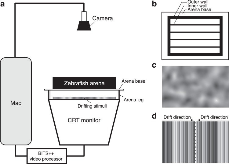
Schematic of the optomotor assay. (a) Stimuli were passed through a BITS++ video processor and displayed on a flat-screen cathode ray tube (CRT) monitor facing upwards. The five-lane zebrafish arena with a transparent base was positioned above the monitor screen, and a camera fixed above the arena obtained digital images of larvae positions before and after each trial. (b) Overhead view of the zebrafish arena, with inner walls dividing the arena into multiple lanes. (c) Stimuli were narrow-band filtered Gaussian-noise textures drifting parallel to the long axis of the arena lanes. (d) Between trials, larvae were corralled to the centre of the lane by high-contrast compound gratings drifting from each end, converging at the midline (dashed white line).

Acknowledgments
This image is the copyrighted work of the attributed author or publisher, and ZFIN has permission only to display this image to its users. Additional permissions should be obtained from the applicable author or publisher of the image. Full text @ Sci. Rep.