
|
Fig. S9
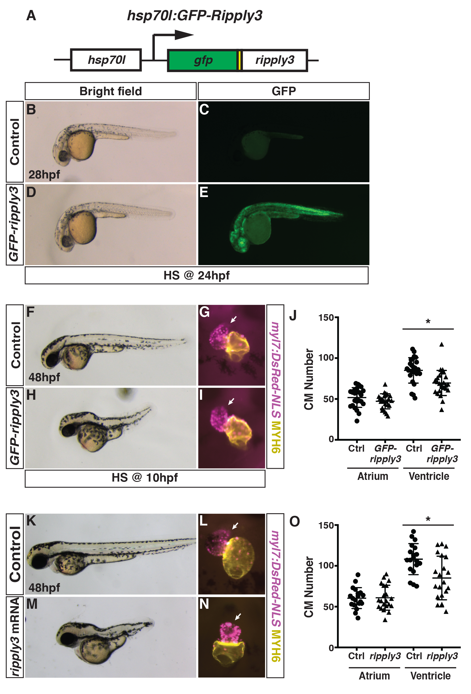
Generation and validation of the heat-shock inducible GFP-ripply3 transgenic line.
(A) Schematic of the heat-shock inducible hsp70l:GFP-ripply3 transgene. (B-E) Heat-shock induction of GFP-ripply3 at 24 hpf. Control embryos are heat-shocked non-transgenic siblings. (F,H) Control and hsp70l:GFP-ripply3 embryos at 48 hpf following heat-shock at 10 hpf. Lateral views with anterior to the left. (G,I) Hearts from control and hsp70l:GFP-ripply3; myl7:NLS-DsRed2 embryos at 48 hpf following heat-shock at 10 hpf. Frontal views. Purple alone indicates ventricle. Yellow indicates atrium. Arrows indicate arterial pole of the ventricle. (J) Quantification of CMs from control and hsp70l:GFP-ripply3; myl7:NLS-DsRed2 embryos at 48 hpf following heat-shock at 10 hpf (n = 25 for control and GFP-ripply3+). (K,M) Control and ripply3 mRNA-injected embryos at 48 hpf. Lateral views with anterior to the left. (L,N) Hearts from control and ripply3 mRNA-injected myl7:NLS-DsRed2 embryos at 48 hpf. Frontal views. Purple alone indicates ventricle. Yellow indicates atrium. Arrows indicate arterial pole of the ventricle. (O) Quantification of CMs from control and ripply3 mRNA-injected myl7:NLS-DsRed2 embryos at 48 hpf (n = 21 for control and ripply3 mRNA-injected embryos).