
|
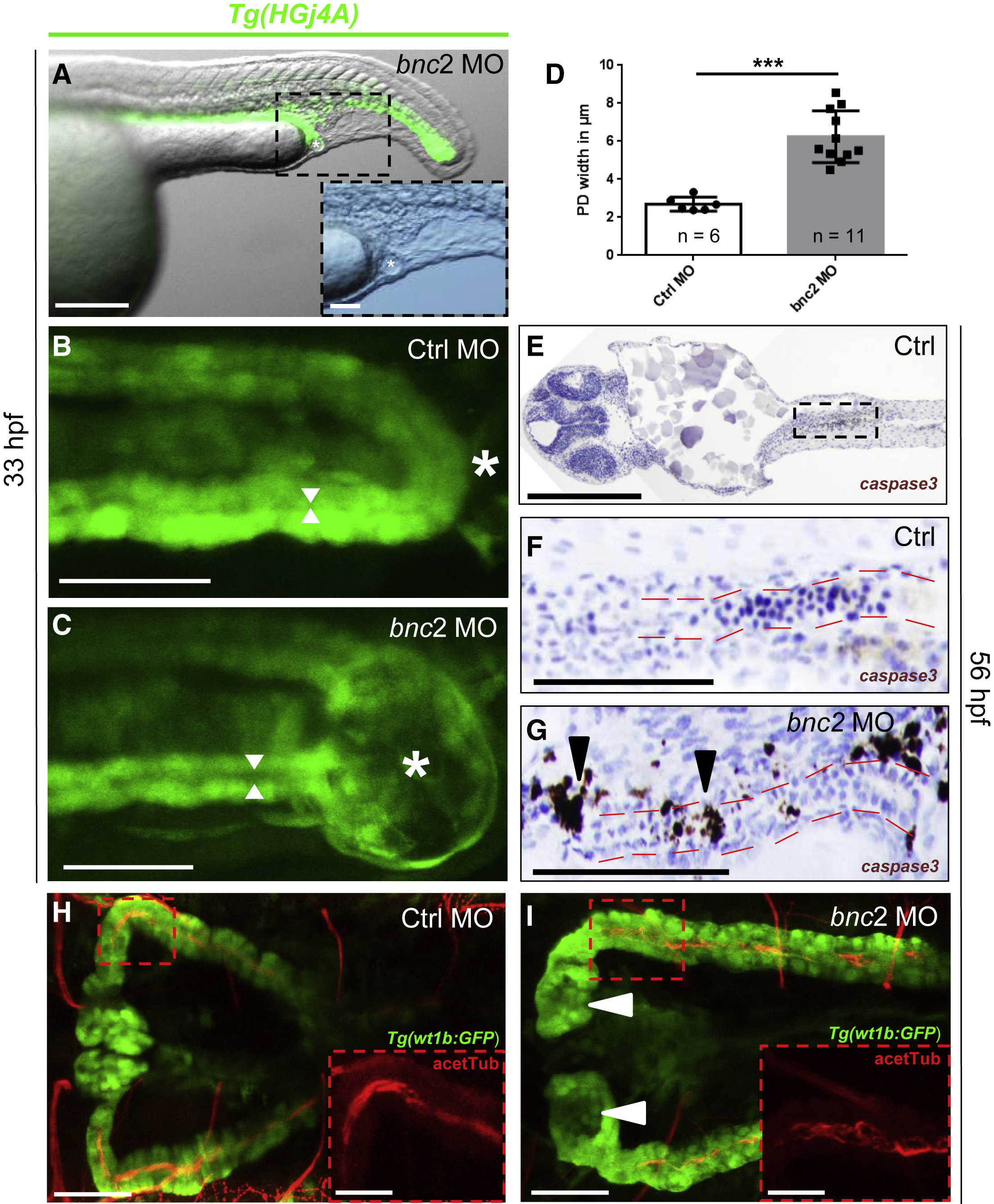
Fig. 4
Distal Pronephric-Outlet Obstruction Is Formed by Pronephric Tissue and Causes Dilated Pronephric Ducts and Increased Apoptosis
(A) Tg(HGj4A) GFP-reporter zfl (lateral view) injected with bnc2 MO emphasize the belonging of the distal pronephric-outlet obstruction, visible as a “vesicle” (marked with a white asterisk), to the distal pronephric duct and cloaca. The enlarged inlay shows the same “vesicle” in the sole bright-field image.
(B and C) High-resolution two-photon microscopy dorsal view of the cloacal region (white asterisks) in Tg(HGj4A) zfl injected with Ctrl MO (B) and bnc2 MO (C) indicates the intimate relation of the pronephric-outlet obstruction to the bilateral pronephric ducts. Widths of the pronephric-duct lumen are indicated with white arrows.
(D) Quantification of pronephric-duct widths in Tg(HGj4A) zfl injected with bnc2 MO shows significantly (p = 0.0002, Student’s t test) dilated pronephric ducts compared to controls. PD = pronephric ducts. Data are presented as means with SEM.
(E–G) Cleaved caspase 3 staining in bnc2 MO-injected zfl (56 hpf) shows an increased rate of apoptosis (black arrowheads in G) compared to Ctrl MO-injected embryos (E–F) around the pronephric duct (marked by red lines), the cloacal region, and the central nervous system (not shown). An overview emphasizing and localizing the pronephric regions shown in (F) and (G) is shown in €.
(H and I) Dorsal image from immunofluorescence staining of acetylated tubulin-stained cilia (red, acetTub) and GFP (green) depicts normal cilia morphology in the pronephric ducts in Tg(wt1b:GFP) zfl injected with Ctrl MO (H) and bnc2 MO (I) at 56 hpf. Pronephric ducts are widened in the bnc2 MO zfl as mentioned before. White arrowheads point to glomerular cysts in the bnc2MO zfl. The sole acetylated-tubulin stain (red channel) emphasizes cilia morphology in the respective enlargement inlays of (H) and (I).
Scale bars represent 200 μm (A), 50 μm (magnification of A–C), 100 μm (E–G), 50 μm (H and I), and 25 μm (magnifications of H and I). ∗∗∗ p < 0.0005.