
|
Fig. 4
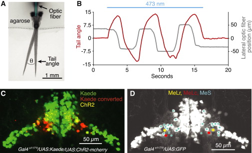
ChR2 Stimulation of nMLF Neurons and Their Localization Using Photoconversion
(A) Dorsal view of the experimental setup used for ChR2 experiments. Two different tail positions are shown to illustrate the tail angle measurement used below and in subsequent figures. Optic fiber is pseudocolored for clarity.
(B) Change in tail angle (red) in a Gal4s1171t/UAS:ChR2 fish, elicited by nMLF stimulation with a laterally moving optic fiber (gray; 10 µm fiber diameter, continuous beam 0.8 mW/mm2). Blue line depicts the epoch of ChR2 stimulation.
(C) Confocal image projection of the midbrain in a Gal4s1171t/UAS:ChR2/UAS:Kaede fish, which underwent bilateral Kaede conversions at sites that produced left and right steering, respectively.
(D) Confocal image projection, detailing the positions of MeLr, MeLc, and the MeS neurons in the lateral nMLF.
See also Figures S4, S5, and Movie S3.