
|
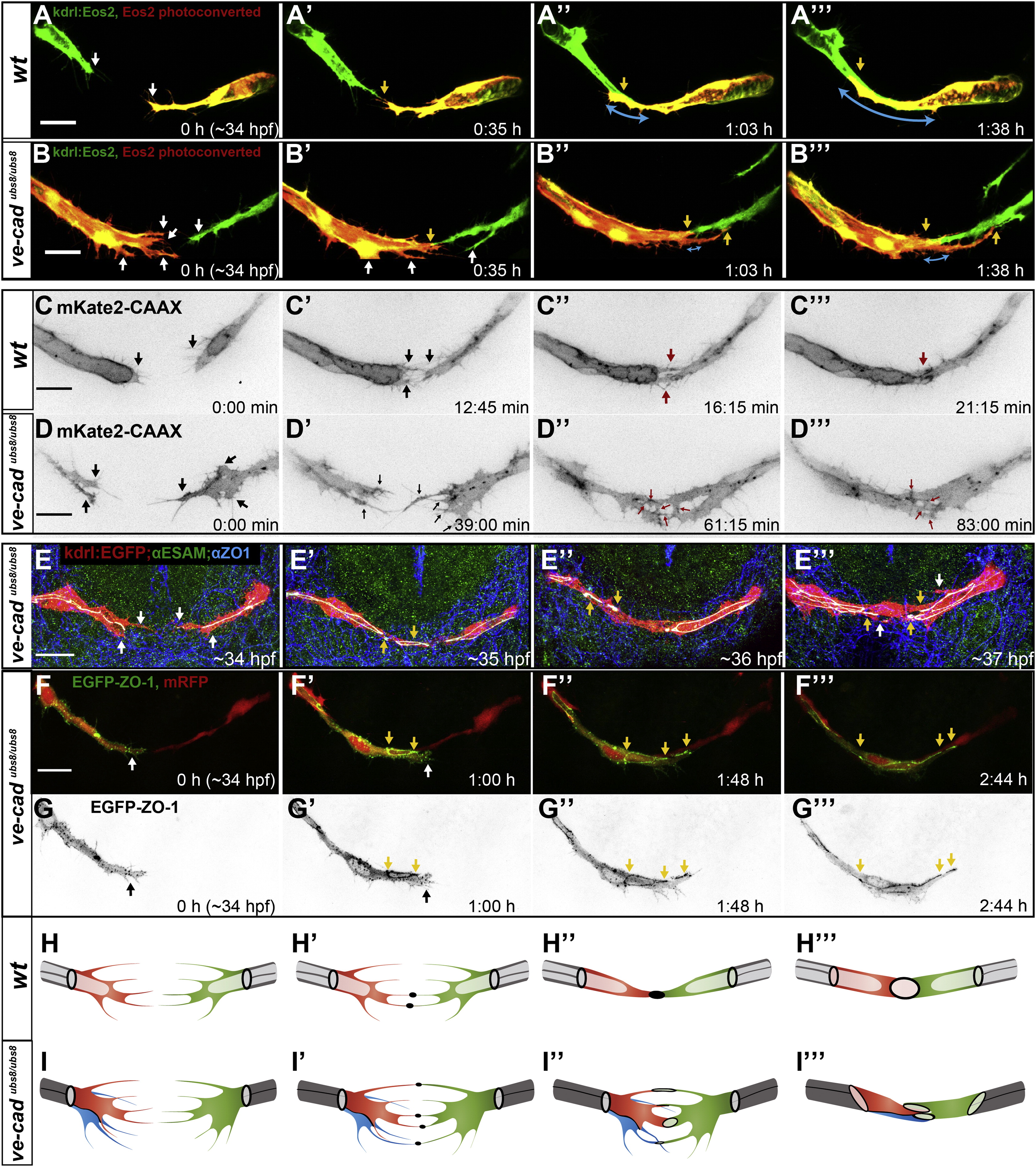
Fig. 7
VE-Cadherinubs8/ubs8 Embryos Show Defects in the Initial Steps of the Fusion Process (A and B) Still pictures of a time-lapse movie showing development of the PLA in a transgenic line ve-cadubs8/ubs8;Tg(kdrl:tdEos2)ubs15; of a wild-type embryo (A) and a ve-cadherinubs8/ubs8 embryo (B). White arrows point at cell extensions, single on each sprout in the wild-type (WT) embryo (A) and multiple in ve-cadherinubs8/ubs8 mutant (B). Upon contact formation, the WT sprouts have one contact point (A2, yellow arrow) and do not form additional extensions, as the contact surface elaborates (A3 and A32, yellow arrows point at the sprout end, blue arrows show the length of the contact surface). The ve-cadherinubs8/ubs8 sprouts form multiple extensions (B2–B32, white arrows) and multiple contact points form between the sprouts (yellow arrows). The continuous contact surface of the sprouts expands slowly (blue arrows). (C and D) Still pictures of spinning disc time-lapse movies showing development of the PLA in transgenic line TgBAC(kdrl:mKate2-CAAX)ubs16 of wild-type (C) and VE-cadherin mutant (ve-cadubs8/ubs8) (D) embryos. Black arrows point at sprouting cell extensions, single or double in WT (C and C2) and multiple in ve-cadherinubs8/ubs8 vessels (D and D2). Red arrows point at cell-cell contacts. These contacts resolve into a continuous contact surface in wild-type (C3–C33), whereas in the mutant they persist over time resulting in a noncontinuous contact surface (D3 and D32). (E) Antibody staining of fusion steps corresponding to images in (A). Ve-cadubs8/ubs8;Tg(kdrl:EGFP)s843 embryos (red) and anti-ZO-1 (blue) and anti-ESAM (green) antibodies were used. Junctions within vessels are visible where signals overlap (white). White arrows mark cell extensions (E). Yellow arrows mark the contact points where junctional proteins are deposited (E2–E32). (F and G) Still pictures of a time-lapse movie showing contact formation in a transgenic embryo ve-cadherinubs8/ubs8;Tg(fliep:GFF)ubs3;(UAS:mRFP);(UAS:EGFP-ZO-1). EGFP-ZO-1 (green in F; black in G) is expressed in only one tip cell. Cell bodies are red (F). Upon contact of the tip cells a junctional ring forms (F2 and G2, yellow arrows), but the cell forms new extensions (white arrow) that form additional contacts with the other sprout (F3 and F32, yellow arrows). (H and I) Cellular models of initial steps of the fusion process in wild-type (H) and ve-cadherinubs8/ubs8 vessels (I). Initially, both sprouts form multiple extensions, which in the wild-type are limited to one to two per tip cell (H and H2) and in the mutant often reach three to five (I and I2). Multiple cells can be present at the leading tip of the mutant sprout (I, red and blue cell) increasing the number of the observed extensions. When the filopodia touch, a contact is established with deposition of new junctional material in the wild-type (H2, black dots) as well as the mutant sprouts (I2, black dots). In the mutant, more contact spots are present. As the contact formation proceeds, the wild-type sprouts merge all the contact sites into one to form a continuous contact surface (H3 and H32), whereas the mutant sprouts fail to merge all the contact sites resulting in multiple and disturbed junctional connections. See also Figure S3 and Movies S8, S9, and S10. Scale bars, 20 μm.
Reprinted from Developmental Cell, 25(5), Lenard, A., Ellertsdottir, E., Herwig, L., Krudewig, A., Sauteur, L., Belting, H.G., and Affolter, M., In Vivo analysis reveals a highly stereotypic morphogenetic pathway of vascular anastomosis, 492-506, Copyright (2013) with permission from Elsevier. Full text @ Dev. Cell