
|
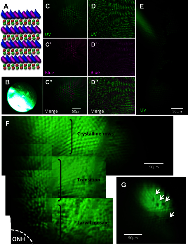
Fig. 2
Viewing the cone mosaic in vivo. A: The cone row mosaic is shown as a schematic (with ultraviolet-sensitive (UV) cones in magenta and blue-, green- and red- sensitive cones coloured as per their respective spectral sensitivity; not to scale). B. The best possible picture equivalent to C acquired without the fundus lens, using standard stereomicroscope optics. C. The cone mosaic can be successfully imaged in vivo; The example here is from fish transgenic for green fluorescent protein (GFP; C) and mCherry [C′] in UV- and blue-sensitive cones, respectively, and merging the two channels [C′′] with mCherry signals pseudocoloured to magenta. D: An ex vivo image of a flat-mounted retina dissected away from other ocular tissues is presented for comparison to [C, D], [D′] and [D′′] show GFP, mCherry and merged channels, respectively. E: Details are visible in vivo after cell ablation, such as lesion edges where GFP-labeled cones have died, leaving clear gaps in the cone mosaic. F: A panorama assembled from stills taken in Appendix 2 (0:08-0:12) depicts several features, including: the crystalline rows of UV cones in the adult row mosaic; the larval mosaic, which does not contain rows; and a transition zone between the mosaics. The optic nerve head (ONH) is located at the bottom left of the panorama. G: An image of UV cone rows with gaps, representing individual absent cones, which was regularly observed. Appendix 1 showing intact photoreceptors, and Appendix 2 of one intact and two lesioned photoreceptor layers, can be found online. n=4 fish shown in this image.