- Title
-
The zebrafish visual system transmits dimming information via multiple segregated pathways
- Authors
- Robles, E., Fields, N.P., Baier, H.
- Source
- Full text @ J. Comp. Neurol.
|
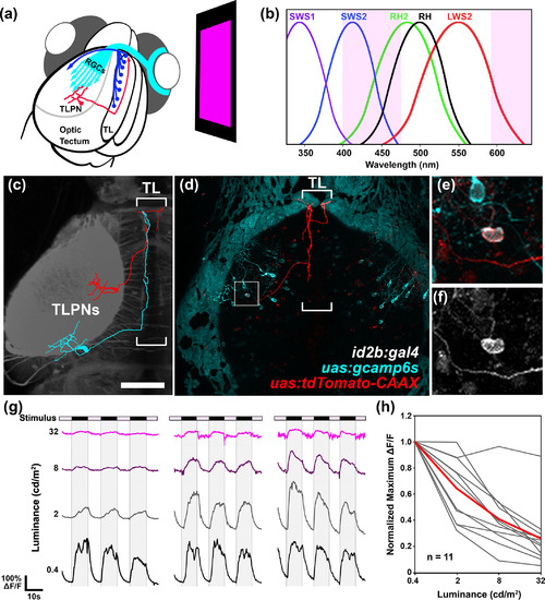
Torus longitudinalis projection neuron (TLPN) responses to whole‐field dimming stimuli. (a) Schematic overview of experiments performed in this study. An organic light‐emitting diode (OLED) screen equipped with magenta filters is positioned in front of one eye of an agarose‐embedded Tg(id2b:gal4,uas:gcamp6s) double transgenic larva, which drives tissue‐specific expression of the calcium sensor protein GCaMP6s. (b) Absorption curves for the photopigments expressed in UV cones (SWS1), blue cones (SWS2), green cones (RH2), red cones (LWS2), and rods (RH1). Region shaded in magenta indicates the wavelength range generated by the OLED stimulus, simultaneously activating rods as well as red, green, and blue cones. (c) Skeletonized tracings of two TLPNs overlayed on a gray scale dorsal view image of Tg(elavl3:LY‐TagRFP) brain containing left tectum and TL. Note that posterior positioned TLPN innervates TL posteriorly, whereas anteriorly positioned TLPN enters TL at its anterior pole and crosses the midline to innervate contralateral TL. (d) Dorsal view of a 7 dpf Tg(id2b:gal4,uas:gcamp6s) larva that was pressure injected at the early embryo stage to yield sparse tdTomato:CAAX labeling within the id2b:gal4 expression pattern. Note sparse tdTomato labeling of a single tectal neuron with an axon that enters TL, extends anteriorly, and crosses the midline within TL. (e) Higher magnification view of boxed regions in (d). (f) GCaMP6s fluorescence of TLPN cell body within boxed region in (d). (g) Example traces of GCaMP6s fluorescence from three individual TLPN neurons during presentation of whole‐field dimming stimuli with the following ON light intensities: 0.4, 2, 8, and 32 cd/m2. All three TLPNs responded maximally to trials with low intensity stimuli (≤2 cd/m2). (h) Effect of stimulus intensity on maximum ∆F/F values during OFF phase for 11 TLPNs during presentation of trials at the following light intensities: 0.4, 2, 8, and 32 cd/m2. Data from individual trials are shown in gray. Average of the 11 individual traces is shown in red. Scale bar: 100 μm in (a), 30 μm in (b) |
|
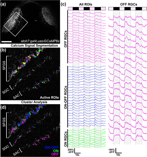
Functional identification of OFF retinal ganglion cell (OFF‐RGC) terminals in vivo. (a) Low‐magnification dorsal view of a 6 dpf Tg(atoh7:gal4,uas:gcamp6s) larva. Boxed region indicates typical field of view used for functional imaging trials. (b) Average intensity projection from a recording in the left tectum of a Tg(atoh7:gal4,uas:gcamp6s) larva presented with dimming stimuli to the right eye. Active regions of interest (ROIs) identified by cross‐correlation‐based image segmentation are displayed in different colors. Note multiple active regions in the SAC/SPV, SGC, and deepest sublayers of SFGS. (c) Fluorescence intensity traces of ROIs indicated in C during repeated presentation of dimming steps to the contralateral eye as indicated by light and dark bars at top. Each trace is 58 s in duration and consists of ON phases of 7‐s duration and OFF phases of 10‐s duration. Gray shading overlaid on traces indicates dimming phase when stimulus display is OFF. k‐means cluster analysis divided ROIs into three groups based on their temporal dynamics, indicated by color coding in blue, green, and magenta. Magenta‐colored traces represent dimming detector RGCs that exhibited strong and consistent OFF responses. (d) Average intensity projection shown in (b) presented with OFF ROI color coding that corresponds to clustering results shown in (c). Note that in this larva OFF‐RGCs ROIs are located in the SAC/SPV, SGC, and deepest sublayers of SFGS (5/6). Data are from 52 ROIs detected in a single larva. Scale bar: 50 μm in (a), 20 μm in (b,d). SAC, stratum album centrale; SFGS, stratum fiibrosum et griseum superficiale; SGC, stratum griseum centrale; SPV, stratum periventriculare |
|
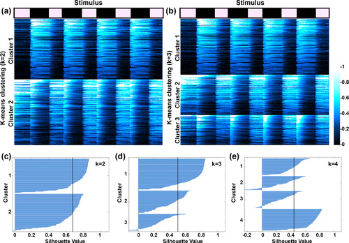
K‐means clustering of automatically segmented retinal ganglion cell (RGC) regions of interest (ROIs). (a,b) Results of ks‐means clustering for 325 individual ROIs from 10 Tg(atoh7:gal4,uas:gcamp6s) tecta using k values of 2 and 3. Stimulus timing is indicated at top, with total recording duration of 75 s (7‐s stimulus‐ON, 10‐s stimulus‐OFF). Fluorescence intensity for each recording is displayed as a color raster plot based on color scale at right. Note that in both (a and b), Cluster 1 is comprised of RGC terminals with strong and consistent OFF responses. (c–e) Silhouette plots for k values of 2, 3, and 4. Vertical gray line in each plot indicates average silhouette value. The highest average silhouette value in (c) indicates that the data are best fit by a k value of 2 |
|
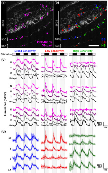
OFF retinal ganglion cells (OFF‐RGCs) are comprised of functional classes with different photosensitivity profiles. (a) Average intensity projection from the left tectum of a 6 dpf Tg(atoh7:gal4,uas:gcamp6s) larva during presentation of 32 cd/m2 dimming stimulus to the right eye. Dimming detector regions of interest (ROIs) identified by cross‐correlation based image segmentation are shown in magenta. (b) Image in (a) with ROI color coding that indicates photosensitivity profile of individual OFF‐RGC terminals. BS (broad sensitivity) ROIs in blue correspond to OFF‐RGC terminals that responded strongly to trials at all stimulus intensities (0.4, 2, 8, and 32 cd/m2). LS (low sensitivity) ROIs in red correspond to OFF‐RGC terminals that responded optimally to trials with high light intensities during the ON phase (>8 cd/m2). HS (high sensitivity) ROIs in green correspond to OFF‐RGC terminals that responded optimally to trials with low light intensities during the ON phase (>8 cd/m2). (c) Sample traces of individual BS, LS, and HS OFF‐RGC terminals in tectum shown in (a and b). Each trace is 58 s in duration and consists of four ON phases of 7‐s duration interleaved with three OFF phases of 10‐s duration. The BS OFF‐RGC responds robustly at all stimulus intensities. In contrast, the LS OFF‐RGC did not respond at low light intensities, whereas the HS OFF‐RGC did not respond at high light intensities. (d) Average intensity traces of BS, LS, and HS OFF‐RGC terminals in the tectum shown in (a and b) (n = 11 ROIs for each group). Error bars represent SD. Scale bar: 20 μm in (a and b) |
|
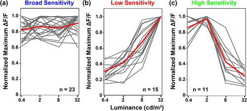
(a–c) Photosensitivity tuning curves for OFF retinal ganglion cells (OFF‐RGCs) detected in tectum of larva used in Figure 4. Individual region of interest (ROI) responses are shown in gray, average of these traces is shown in red. Data are presented as peak ∆F/F normalized to the maximum value for each RGC ROI in any of the trials. Data represents 59 ROIs detected in three larvae. Note diversity of responses within each functional class |
|
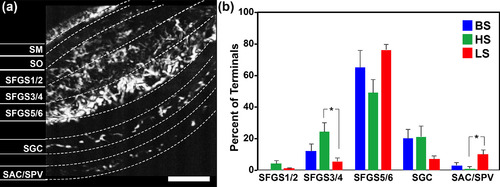
Layer‐specific innervation of tectum by broad sensitivity, high sensitivity, and low sensitivity OFF retinal ganglion cell (OFF‐RGC) terminals. (a) Average intensity projection of a recording from the tectum of a Tg(atoh7:gal4,uas:gcamp6s) double transgenic larva during stimulus presentation. Overlaid are sublayer boundaries used for tectal sublayer designations. (b) Distribution of OFF‐RGC classes by tectal neuropil sublayer. Data represents 290 regions of interest detected in eight larvae. Scale bar: 20 μm [Color figure can be viewed at |
|
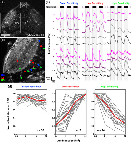
Optic tectum contains dimming‐responsive neurons with different photosensitivities. (a) Low‐magnification dorsal view of a 6 dpf Tg(Elavl3:gal4,uas:gcamp6s) larva. Boxed region indicates typical field of view used for functional imaging trials. (b) Average intensity projection from a recording in the left tectum of a 6 dpf Tg(elavl3:gal4,uas:gcamp6s) larva presented with light steps to the right eye. Region of interest color coding indicates photosensitivity profile of dimming‐responsive tectal neurons: broad sensitivity (BS; blue), low sensitivity (LS; red), and high sensitivity (HS; green). Note sparse and dispersed distributions of neurons in both the neuropil (NP) and periventricular (SPV) layers of the tectum. (c) Sample traces of individual BS, LS, and HS tectal neurons. Each trace is 58 s in duration and consists of four ON phases of 7‐s duration interleaved with three OFF phases of 10‐s duration. (d) Photosensitivity tuning curves for 73 dimming‐responsive neurons (BS, LS, and HS) detected in 10 tecta (gray). Average of individual traces is shown in red. Scale bar: 80 μm in (a), 40 μm in (b) |
|
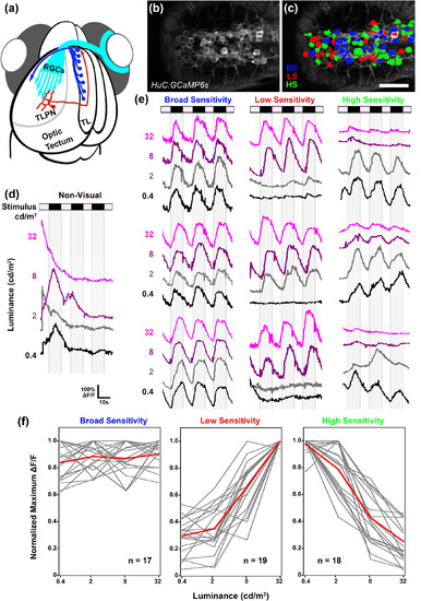
Parallel dimming pathways remain segregated in torus longitudinalis (TL). (a) Schematic of retinal ganglion cell innervation of the tectum and reciprocal connection between the tectum and TL. (b) Single multiphoton image from a recording in the TL of a 6 dpf Tg(elavl3:gal4,uas:gcamp6s) larva presented with light steps to the right eye. Anterior is to the right. (c) Region of interest color coding indicates photosensitivity profile of individual TL neurons: broad sensitivity (BS; blue), low sensitivity (LS; red), and high sensitivity (HS; green). Note dense activation of many neurons on both sides of the TL. Anterior is to the right. (d) Sample trace of a nonvisual TL neuron. Note large events that are highly variable with respect to stimulus timing across trials. (e) Sample traces of individual BS, LS, and HS TL neurons. Each trace is 58 s in duration and consists of four ON phases of 7‐s duration interleaved with three OFF phases of 10‐s duration. Note that in several traces, baseline drifted in either the positive or negative direction. (f) Photosensitivity tuning curves for 54 dimming‐responsive neurons detected in TL (gray). Average of individual traces is shown in red. Scale bar: 40 μm [Color figure can be viewed at |

