
- Title
-
Synergistic interaction of sprouting and intussusceptive angiogenesis during zebrafish caudal vein plexus development
- Authors
- Karthik, S., Djukic, T., Kim, J.D., Zuber, B., Makanya, A., Odriozola, A., Hlushchuk, R., Filipovic, N., Jin, S.W., Djonov, V.
- Source
- Full text @ Sci. Rep.
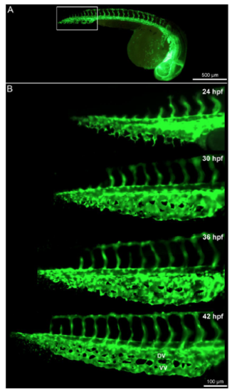
Time lapse in vivo images of the caudal vein plexus (CVP) from 24-42 hpf. (A) Overview of the blood vessels in Tg(fli1a:eGFP)y7 of the whole zebrafish embryo with the highlighted region (white box) showing the developing CVP. (B) In vivo still images of the CVP from selected ages between 24 hpf and 42 hpf indicating the mode of angiogenesis. Sprouting and anastomoses are evident at 24 hpf while pillar formation starts from 30 hpf increasing in intensity towards 42 hpf. |
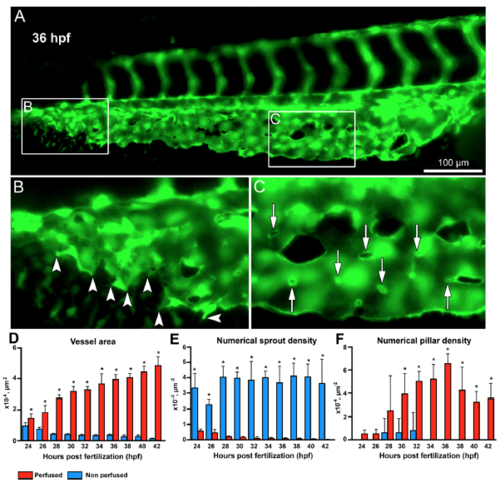
Morphometric analysis of sprouting vs.intussusceptive angiogenesis between perfused and non-perfused regions of the zebrafish CVP. (A) At 36 hpf the zebrafish embryo shows both intussusceptive and sprouting angiogenesis. (B) The box B in the distal region of the CVP is marked to show the sprouts in the non-perfused region with the arrowheads pointing to the corresponding enlarged image. (C) The box C in the proximal region of the CVP shows the pillars in the perfused region marked with white arrows in the corresponding enlarged image. (D) The bar graph represents the vessel area (VA) of the zebrafish CVP, the VA in the perfused region is significantly (p < 0.05) increased in comparison with the non-perfused region. (E) The numerical sprout density (i.e. number of sprouts/vessel area) is significantly (p < 0.05) increased in the non-perfused region compared to the perfused region. (F) While the numerical pillar density (i.e. number of pillars/vessel area) increases with time reaching the maximum pillar density at 36 hpf and subsequently decreases due to pillar fusion and splitting, the values represented in the graph are mean ± SD (n = 4). Asterisks (*) indicate significant increase. |
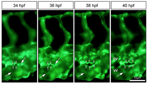
In vivo imaging of intussusceptive pillar formation followed by fusion and splitting in the CVP of zebrafish embryo. The large white arrows represent a clear vessel at 34 hpf and newly formed pillars (appearing as a tiny holes) in the same region of observation at 36 hpf. The small white arrows show pillar fusion and splitting of the dorsal (DV) from the ventral (VV) vein in between from 36-40 hpf. For further information, see Movie S2. |
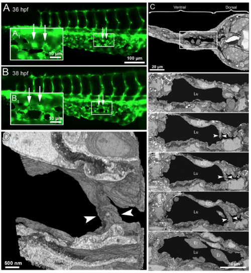
Serial block face electron microscopy (SBF-EM) demonstrating the 3D ultra-structure of newly formed intussusceptive pillar. (A) In vivo GFP images of CVP at 36 hpf, revealing intact vascular surface; the site of future pillar formation is indicated by white arrows. (A 1 ) Symbolizes the rectangle in A at higher magnification. (B,B 1 ) At 38 hpf in the area of interest dark dots (indicated by arrows) represent the newly-formed pillars. (C) Overview of the SBF-SEM transverse section of zebrafish embryo (each slice measuring 75 nm thick) shows the dorsal and ventral regions at 38 hpf and the ventral region with the CVP is indicated in the white rectangle. (C 1 –C 4 ) Corresponding to CVP serial sections (650, 677, 682, 690 and 693) illustrating the ultra-structure of a trans-luminal intussusceptive pillar (indicated by arrowheads). The other structures in the CVP like endothelial cells (EC), erythrocytes (Er) and vascular lumen (Lu) are respectively indicated. (D) Represents the 3D reconstruction of intussusceptive pillar (indicated with large arrowheads) corresponding to the proximal one in B1 and to the C1–C4 SBF-SEM sections. For further information, see supplementary Movie S4. |
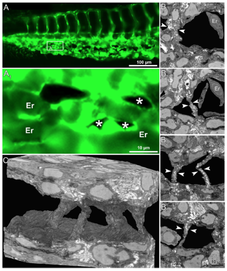
In vivo images and serial block face electron microscopy (SBF-SEM) sections obtained during IA mediated remodeling of zebrafish CVP. (A) In vivo images of CVP from zebrafish embryo and the corresponding region of interest (A 1 ) in the GFP image of intussusceptive pillars (indicated by asterisk) shown at higher magnification. (B-B3) Representative SBF-SEM images showing a set of 4 pillars found in the distal region of the remodeling CVP (series of sections comprising 500 slices, each with 50 nm thickness). (C) Three dimensional reconstruction of SBF-SEM sections illustrates the volume of intussusceptive pillars. Erythrocytes have been removed in order to demonstrate the spatial orientation of three pillars. For further information, see Supplementary Movies S5 and S6. |
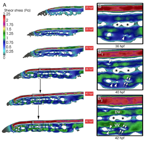
Shear stress distribution during CVP development. (A) The overall shear stress distribution calculated from blood flow videos obtained from in vivo microscopy between 25-42 hpf of developing CVP. (B,B 1 ) Arrowheads show the appearance of pillars in the regions of declining shear stress. (B 1 ,B 2 ) Subsequently the same shear stress profile is associated with the path of pillar fusion indicated in white double arrows leading to the splitting of the vessel. The ensuing splitting of the vessels between 36-42 hpf leading to the formation of dorsal (DV) and ventral vein (VV). The splitting path is indicated with asterisks. |
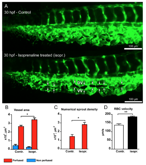
Isoprenaline hydrochloride (Isopr.) treatment accelerates vascular development and splitting in the zebrafish CVP. (A) CVP of the control embryo at 30 hpf compared with that of isoprenaline-treated embryo. The white double arrows marked in the treated CVP represent advanced vascular splitting and segregation of the DV and VV in comparison to the control CVP. (B) The treated CVP resulted in significant increase in vessel area and (C) increased numerical pillar density in the perfused region. (D) The treated embryos showed significant increase in RBC velocity compared to non-treated zebrafish embryos. |
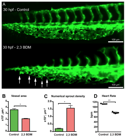
Treatment with 2,3 BDM decreases CVP development in zebrafish embryos. (A) The CVP of the control compared with 2,3 BDM treated embryos at 30 hpf. The treated CVP shows numerous sprouts (white arrows) and delay in growth at 30 hpf in comparison with the control. (B) The 2,3 BDM treated CVP shows significant decrease in vessel area. (C) The numerical sprout density has increased immensely in the treated embryos. (D) The heart rate of the 2,3 BDM treated embryos shows significant decrease compared to control embryos at 30 hpf. |
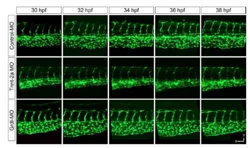
Morpholino (MO) antisense oligonucleotides microinjected CVP between 30-38 hpf. The control MO injected CVP shows normal CVP development, which remodels with time. While tnnt-2a and gridlock MO injected embryos show impaired CVP development along with the dramatically reduction in pillar formation. Scale bar x-axis = 50 μm; y-axis=32 μm. See also supplementary figure S3. |
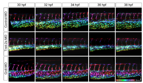
Morpholino (MO) antisense oligonucleotides microinjected CVP between 30-38 hpf. Z-stacks of the CVP were depth image-coded according to their z positions. The color code bar represents the scanning from proximal to distal regions of the CVP. |