
- Title
-
Endothelial Cell Self-fusion during Vascular Pruning
- Authors
- Lenard, A., Daetwyler, S., Betz, C., Ellertsdottir, E., Belting, H.G., Huisken, J., Affolter, M.
- Source
- Full text @ PLoS Biol.
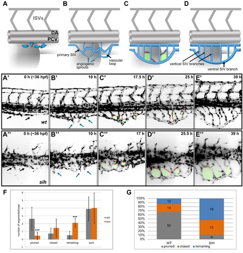
SIV development and maturation (A-D) A model representing four phases of SIV plexus development in the zebrafish embryo between ~36 and 84 hpf. The SIV plexus is blue, and the dorsal aorta (DA), posterior cardinal vein (PCV), and intersegmental vessels are marked in grey. Single endothelial cells sprout ventrally and separate from the PCV (A) to form a primary SIV branch (B). Angiogenic sprouts grow out of the primary SIV and fuse to each other, forming a reticular plexus with multiple cross branches (C, red) and vascular loops (C, green); simultaneously, the plexus grows and moves ventrally. Eventually, the cross branches (and hence the loops) are removed, and the plexus simplifies, forming a set of parallel vertical branches draining into a large ventral SIV branch (D). (A′-E′) Stills from a SPIM time-lapse movie representing five phases of SIV development corresponding to models in A. (A′′-E′′) Stills from a SPIM time-lapse movie representing SIV development in a silent heart morphant embryo corresponding to models in A. In this case, the SIV keeps its reticular structure because of impaired pruning. (F) A graph comparing the SIV vascular loop formation and remodeling in a wild-type (grey) and silent heart embryo (orange), based on SPIM time-lapse experiments between 36 and 84 hpf. From the left, showing the number of cross branches pruned during remodeling phase, the number of cross branches/loops closed via collateral fusion, the number of cross branches/loops remaining until the end of the movie, and the sum of all loops observed throughout the movie. The values are average numbers per SIV plexus with standard deviation (n = 19 for wild type [WT] and n = 9 for silent heart [SIH]). *** p < 0.001. (G) A graph showing the percentage contribution of pruned (grey), closed by collateral fusion (orange), and remaining (blue) vascular loops to all events observed in WT versus silent heart embryos. See also S1 and S2 Figs, S4 Movies, S1 Data. |
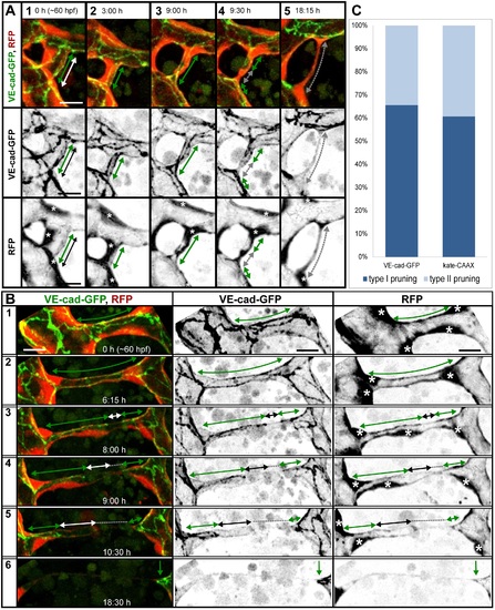
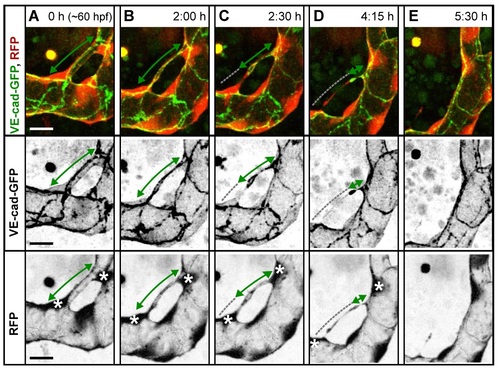
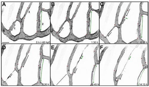
Cell rearrangements during pruning of type I and II. Stills from time-lapse movies illustrating cell rearrangements in type I pruning with lumen collapse before cell rearrangements (A) and type II pruning with cell rearrangements before lumen collapse (B) in transgenic embryos Tg(fliep:GFF)ubs3,(UAS:mRFP),(5xUAS:cdh5-EGFP)ubs12. Cell–cell junctions are green (VE-cad-EGFP), and cell cytoplasm is red. Black-and-white pictures show respective channels alone. Key steps of pruning are shown. Green arrows mark multicellular contacts (cell–cell junction length), white arrows mark transcellular lumen, and grey dotted lines mark unicellular fragments without lumen. Asterisks mark nuclei of cells contributing to the branch. (A) Pruning type I. A small, lumenized branch is made of two cells connected by two parallel lines of junctions (1). Lumen collapses when the branch is still multicellular (2–3); after lumen collapse, cells move away from each other, and cell–cell contact surface shrinks, generating a nonlumenized, ajunctional segment (4). Eventually, only the last bridging cell remains (5, grey arrow) prior to final detachment (not shown). See also S8 and S9 Movies and S3 Fig. (B) Pruning type II. Cellular architecture of a multicellular branch (1) is simplified to a branch made mainly by two cells connected by parallel lines of junctions (2). Further cell rearrangements lead to the formation of a partially unicellular tube (3). The lumen eventually collapses (4), and the cell body migrates towards the left-side major branch (5) until only a last, narrow cell extension connects two major branches (6). See also S10 Movie. (C) A graph representing percentage of pruning type I (dark blue) and II (light blue) in all pruning events analyzed in transgenic embryos of Tg(fliep:GFF)ubs3,(UAS:mRFP),(5xUAS:cdh5-EGFP)ubs12 and TgBAC(kdrl:mKate-CAAX)ubs16, respectively. Scale bar: 10 µm. |
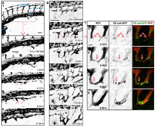
SIV outgrowth involves single cell assembly and angiogenic sprout fusion. Stills of time-lapse movies showing outgrowth of the SIVs between ~36 and ~60 hpf in transgenic embryos: Tg(fli1a:EGFP) in A and Tg(fliep:GFF)ubs3,(UAS:mRFP), (5xUAS:cdh5-EGFP)ubs12 in B and C. (A) SIV emerges from the PCV at ~36 hpf (1–2). Single cells sprout ventrally from the PCV (2–3, arrows). The cells that contact each other (4, arrows) often lose contact with the PCV. A single, nonlumenized primary SIV forms and produces ventral angiogenic sprouts (5, arrows) and eventually lumenizes (6). PCV, posterior cardinal vein; DA, dorsal aorta; CCV, common cardinal vein; ISV, intersegmental vessel; DLAV, dorsal longitudinal anastomotic vessel. See also S3 Movie. (B) Multiple angiogenic sprouts originating from the primary SIV connect to each other (arrows) before (1–3) and after (4–6) lumen inflation, forming a net of vascular loops. (C) Close-up of SIV sprout fusion including the VE-cad-EGFP channel, showing new contact formation (2, arrow marks a spot of junctions), contact expansion (3, a ring of junctions), and transformation of the new branch into a multicellular tube (lines of junctions in 4). See also S4 Movie. Scale bars: 50 µm (A and B) and 10 µm (C). |
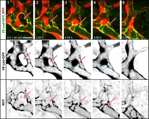
Closing of a vascular loop by collateral vessel fusion. A small branch forms a vascular loop with the major branches (1, arrow). The opening of the loop shrinks as the small branch approaches the major branch sidewise (2–3, arrows). The last very small opening is closed as the side walls of two vessels touch (5) and eventually connect to form a single lumen (6). Fusing lumens of the branches are marked with blue arrows. Scale bars: 10 µm. See also S5 Movie. |
Final steps of pruning type I. A small, lumenized branch is made of two cells (A). Lumen collapses when the branch is still multicellular (B); after lumen collapse, cells move away from each other, and the cell–cell contact surface shrinks (C). The last cell–cell contact (D, green arrow) is eventually resolved completely as the last cytoplasmic extention of the bridging cell detaches from the major branch (E). See also S9 Movie. |
Analyses of pruning vessel with the cell membrane marker. The TgBAC(kdrl:mKate-CAAX) transgenic line allows visualization of the endothelial cell membranes. Transcellular lumen formation and collapse can be distinguished by the presence of inflated, round-ended, apical membrane compartments (black arrows). In certain cases, it is also possible to recognize multicellular vessel fragments by the increase in staining density at the cell–cell contact surfaces (green arrows). The nuclei are recognizable as round structures that are brighter because the two membranes (apical and basal) are well separated around the nucleus (red asterisks in the vessels of interest). These criteria were used for quantifications presented in Fig 3C. Three pruning vessel segments are followed in this figure. Segment 1: lumen in a unicellular vessel fragment (black arrow) is parted next to the nucleus (red asterisk). The lumen perfuses (B) and deflates again (C) to finally collapse completely (D) when the vessel detaches (E, dotted line). Segment 2: a multicellular vessel fragment with the cell–cell contacts visible as darker lines of the membrane staining (A–D, green arrows) narrows significantly when the lumen collapses (E–F). Cells leave the branch after the lumen collapse (D–F, asterisks mark the nuclei). Segment 3: a unicellular vessel fragment undergoes cell division generating two nuclei (C, asterisks), a new cell–cell contact surface (C, green arrow), and two luminal compartments (C, black arrows). The lumen is partially restored (D) but later collapses, leaving a small vacuole-like structure (E, black arrow). The last cell–cell contact surface is reduced as the pruning proceeds (E–F). See also S11 Movie. |
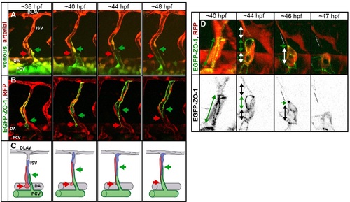
Pruning in the ISVs. (A) Stills of a time-lapse movie showing segmental vein formation in a transgenic embryo Tg(fliep:GFF)ubs4; Tg(UAS:Kaede)rk7. Arterial cells are marked in red, venous cells are green (photoconverted Kaede, colors are inverted for better visualization). A new venous sprout (green arrow) grows out of the PCV towards a segmental vessel (red arrow). The venous sprout connects to the ISV. At the same time, the ISV segment connected to the aorta narrows and eventually detaches as the cells migrate up to contribute to the dorsal part of the ISV. See also S12 Movie. (B) Still images of the segmental vein formation in a transgenic embryo Tg(fliep:GFF)ubs4; Tg(UAS:mRFP);Tg(UAS:EGFP-ZO-1)ubs5. A single cell is expressing the EGFP-ZO-1 (green). The cell belongs to the ISV and is anchored in the DA (red arrow points to the ring-like junction). When the venous sprout connects (green arrow), the green cell moves up the ISV. The junctional ring gradually reduces in size to a spot, and the cell eventually detaches from the aorta and migrates up the ISV. See also S13 Movie. (C) A cellular model of pruning during the segmental vein formation. Arteries are grey, and venous cells are green. Red and blue cells are initially connected to the DA. As the venous sprout attaches to the ISV, the arterial cells detach from the DA and move up to contribute to the dorsal part of the ISV. (D) Stills from a time-lapse movie showing multicellular-to-unicellular tube transformation during pruning in an ISV in a transgenic embryo Tg(fliep:GFF)ubs4; Tg(UAS:mRFP);Tg(UAS:EGFP-ZO-1)ubs5. Key steps of pruning are shown, corresponding to the model in Fig 6. Green arrows mark multicellular contacts (cell–cell junction length), white arrows mark transcellular lumen, and grey dotted lines mark unicellular fragments without lumen. |