
- Title
-
The Tangential Nucleus Controls a Gravito-inertial Vestibulo-ocular Reflex
- Authors
- Bianco, I.H., Ma, L.H., Schoppik, D., Robson, D.N., Orger, M.B., Beck, J.C., Li, J.M., Schier, A.F., Engert, F., and Baker, R.
- Source
- Full text @ Curr. Biol.
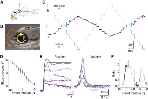
Compensatory Ocular Counterrotations after Changes in Head Tilt(A) Definition of the pitch-tilt axis for head rotation (φ), centered about the ear.(B) Definition of the torsional axis for ocular rotation (ψ), centered at the eye.(C) Example raw eye position trace from a representative 10 dpf larva presented with 1.5 cycles of 10° steps covering the ±60° range.(D) Final eye position observed for each step, for this example 10 dpf larva. Vertical lines are mean ± SD measured over the last 3 s of each step, gray line plots the fit to sine-transformed head rotation.(E) The average response for each colored step type from (C). Black represents the step stimulus. Data shown in both the position and velocity domains (left and right, respectively).(F) Gain (peak eye speed/peak head speed) for the individual steps that progressively rotated the fish from +60° (nose-down) through horizontal to 60° (nose-up) and then back again. Vertical lines are mean ± SD. Colors as in (C) and (E).See also Figure S1. |
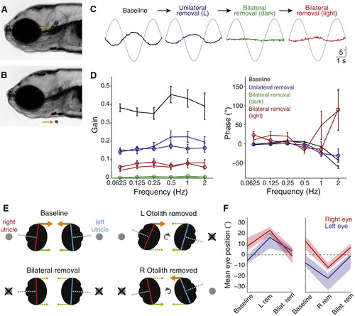
Otolith Removal(A) Lateral view of a 5 dpf larva (anterior left). Arrow points to the utricular otolith.(B) Surgical removal of the utricular otolith. Note the collapse of the otic vesicle after surgery.(C) Example traces from a representative fish (left eye), showing torsional eye movement responses to a 0.25 Hz sinusoidal stimulus after sequential perturbations: baseline performance before surgery, after removal of only the left otolith, after both otoliths are removed, and after both are removed and tilt stimuli were delivered in the light (in all other cases fish were tested in the dark).(D) Bode plots of gain and phase for utricle removal experiments. Lines with open symbols represent right eye data, lines without represent left eye data. We combined data for experiments in which the left otolith was removed first (n = 6) and in which the right otolith was removed first (n = 4) because for both eyes, removal of either otolith had similar effects. Data are shown as mean ± SEM. Phase data are not shown for the “Bilateral removal (dark)” condition because this parameter can not be accurately estimated when gain approaches zero.(E) Schematic representation of the vertical eye positions that were measured under different experimental conditions. By viewing the larvae head-on, the long axes of the right (red) and left (blue) eyes were measured to determine vertical eye position. Orthogonal visual axes are shown in gray, the predicted superior extraocular muscle forces are shown in orange, and inferior muscle forces in green.(F) Summary vertical eye position data, presented as median ± interquartile range for experiments in which the left utricular otolith was removed first (left, n = 10) or the right otolith was removed first (right, n = 4).See also Figure S3 and Movies S1 and S2. |
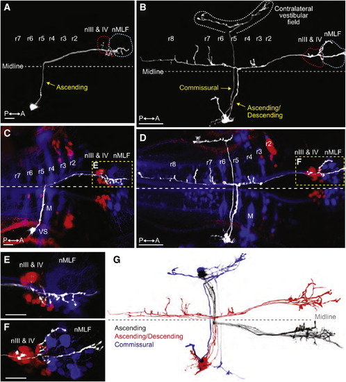
Tangential Neurons Project from the Octavolateral Hindbrain to Contralateral Extraocular Motoneurons(A and B) Projections of two-photon image stacks showing the morphology of tangential neurons in 6 dpf larvae, which were labeled by focal electroporation.(A) An ascending tangential neuron with a cell body in the right tangential nucleus.(B) An ascending/descending neuron and a commissural neuron, both with soma in the right tangential nucleus.(C–F) Double retrograde labeling of the same larvae shown in (A) and (B). Fluorescent dextrans were applied to the rostral spinal cord to label reticulospinal neurons (blue) and to the orbit to label extraocular motoneurons (red).(C) The cell body of the ascending neuron is visible in lateral rhombomere (r) 5, immediately caudal to the vestibulo-spinal (VS) neurons in r4. M indicates the Mauthner cell. Axon terminal arbors are located in nIII, nIV, and the nucleus of the MLF (nMLF) on the opposite side of the brain, shown at higher magnification in (E).(D) Double retrograde labeling showing the projection patterns of the neurons in (B). The commissural neuron projects to the contralateral vestibular field. The ascending/descending neuron extended axon collaterals into various parts of the reticular scaffold in additional to the rostral arborizations adjacent to the ocular motoneurons and the nMLF (shown at higher magnification in F).(E and F) Higher magnification images of (C) and (D), respectively.(G) Two-photon projections of individual tangential neurons, overlaid and color-coded to show the stereotypical morphology of ascending (black, n = 5), ascending/descending (red, n = 4), and commissural (blue, n = 2) subtypes. Images were manually scaled and aligned to allow comparison of cell morphologies. All of the ascending and ascending/descending neurons projected to ocular motonuclei on the contralateral side of the brain.All images are dorsal views, anterior right. Scale bars represent 10 μm for (A) and (C) and 50 μm for (B) and (D)–(F). See also Figure S4 and Movies S3 and S4. |
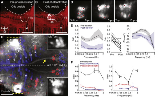
Tangential Nucleus Neurons Are Required for the VOR(A–C) Labeling of the tangential nucleus with C3PA-GFP in a lyn-mCherry background.(A) Lyn-mCherry expression (red) revealed the location of the Mauthner cell (M) and vestibulo-spinal neurons (VS), which served as landmarks allowing us to target the tangential nucleus (Tan) in r5.(B) After photoactivation, a cluster of cells in the left Tan nucleus is visible (white).(C) Axonal projections to nIII, nIV, and nMLF were visible after bilateral labeling of tangential nuclei. The yellow arrow indicates axons ascending in the left MLF, derived from right-sided photoactivated Tan neurons. Insets show the photoactivated tangential nuclei, with dynamic range adjusted to reveal the cell bodies.(D) Three optical sections through the right tangential nucleus of the same larva shown in (C). Photolabeled neurons were individually ablated by spiral-scanning a pulsed infrared laser beam that was centered on the somata of each neuron in turn (red spots).(E) Laser ablation of C3PA-GFP-labeled tangential neurons caused a substantial reduction in the gain of the VOR. Left panel shows Bode plot of gain, presented as median ± interquartile range (n = 12). Middle panel shows change in mean gain across frequencies for all 12 larvae. Right panel shows Bode plot of phase.(F) Data from two fish that displayed the greatest reduction in gain after tangential ablation. Data shown as mean ± SEM. Torsional eye rotations could be evoked by visual input at low frequencies.All images are dorsal views, anterior right. Scale bars represent 50 μm. See also Figure S5. |
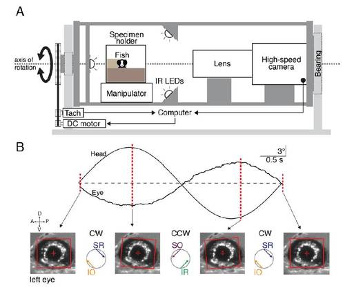
Apparatus for measuring the VOR and accompanying example data, (related to Figure 1). |
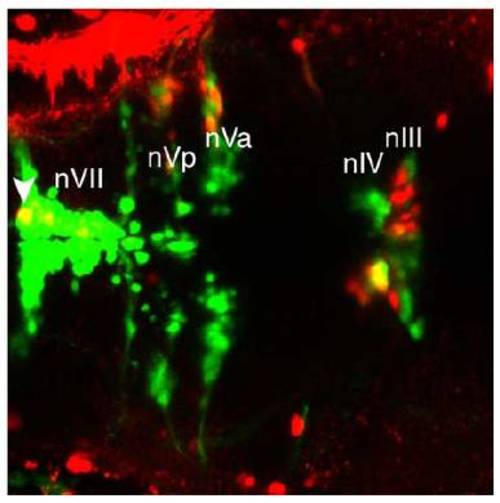
Retrograde dye tracing from the orbit labels nIII and nIV, (related to Figure 4). |
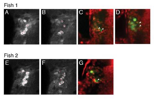
Laser ablation of single, identified, tangential nucleus neurons, (related to Figure 5). |